
Energy-saving biogas system for pig farms

A biogas and pig farm technology, applied in gas production bioreactors, bioreactors/fermenters for specific purposes, biochemical instruments, etc. The effect of high fermentation efficiency and improved production efficiency

Inactive Publication Date: 2015-11-18
陈守亮
View PDF15 Cites 2 Cited by
  • Summary
  • Abstract
  • Description
  • Claims
  • Application Information

AI Technical Summary

Problems solved by technology

The existing biogas system has the following problems: First, the heat is lost quickly in the cold winter environment, the fermentation efficiency of the biogas digester is low, and the amount of biogas produced is significantly reduced
Secondly, although there is a scheme in the prior art to use solar heating to heat up the biogas digester, this method is greatly limited by the intensity of light. The thermal effect is not ideal and the ambient temperature is generally low, resulting in low fermentation efficiency, and the continuous and effective operation of the biogas system still cannot be realized; while the production of livestock manure in farms does not decrease due to changes in light intensity, resulting in the existing biogas The system has the problem of low biogas production and untimely treatment of manure in cold weather with insufficient sunlight
Finally, in the prior art, the waste water after fermentation in the biogas digester is turbid, and the reuse benefit is low. In the prior art, it is mostly discharged directly as water for farmland irrigation, but in actual production, the daily discharge of waste water after fermentation in the farm is relatively large

Method used


Image

  • Energy-saving biogas system for pig farms

Examples


Embodiment Construction

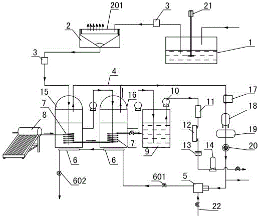
[0021] figure 1 It is the best embodiment of the present invention, below in conjunction with attached figure 1 The present invention will be further described.

[0022] refer to figure 1 , an energy-saving biogas system for pig farms of the present invention, comprising a manure-water mixture pool 1, a pipeline at the outlet of the manure-water mixture pool 1 is connected to a filter pool 2, and a pipeline between the manure-water mixture pool 1 and the filter pool 2 is provided with There is a delivery pump 3, and the liquid outlet end of the filter tank 2 is connected to the biogas generating mechanism through the fecal water delivery pipeline, and the gas outlet end of the biogas generating mechanism is connected to the biogas boiler 5 through the biogas output pipeline 4, and the water inlet end of the biogas boiler 5 is connected to the tap water supply pipe The water outlet of the biogas boiler 5 is connected to the floor heating coil 6 through the pipeline, and the f...


PUM


Abstract

The invention relates to an energy-saving biogas system for pig farms, belonging to the technical field of biogas utilization. A liquid outlet end of a manure-water mixture tank (1) is connected with a filter tank (2) through a pipeline; the pipeline between the manure-water mixture tank (1) and filter tank (2) is provided with a transfer pump (3); a liquid outlet end of the filter tank (2) is connected with a biogas generation mechanism through a manure-water transfer pipeline; a gas outlet end of the biogas generation mechanism is connected with a biogas boiler (5) through a biogas output pipeline (4); a water inlet end of the biogas boiler (5) is connected with a tap water supply pipeline; a water outlet end of the biogas boiler (5) is connected with a floor heating coil pipe (6) through a pipeline; the floor heating coil pipe (6) is positioned below the biogas generation mechanism; a heat exchange casing (7) is arranged in the biogas generation mechanism; and a liquid inlet end of the heat exchange casing (7) is connected with a solar heat exchanger (8) through a pipeline. The energy-saving biogas system for pig farms can keep higher biogas generation efficiency in a cold environment, and can purify and reutilize the manure water.

Description

technical field [0001] An energy-saving biogas system for pig farms belongs to the technical field of biogas utilization. Background technique [0002] The biogas system is a system commonly used in farms to process livestock manure. In the prior art, the biogas system usually transports the manure produced by livestock to the biogas digester through pipelines for processing, and is used to generate biogas and biogas residue. The existing biogas system has the following problems: firstly, in the cold environment in winter, the heat is lost quickly, the fermentation efficiency of the biogas digester is low, and the amount of biogas produced is significantly reduced. Secondly, although there is a scheme in the prior art to use solar heating to heat up the biogas digester, this method is greatly limited by the intensity of light. The thermal effect is not ideal and the ambient temperature is generally low, resulting in low fermentation efficiency, and the continuous and effect...

Claims


Application Information

Patent Timeline
IPC IPC(8): C12M1/38C12M1/36C12M1/12C12M1/107C12M1/02
CPCC12M21/04C12M27/02C12M37/02C12M41/12C12M41/26C12M43/00Y02E50/30
Inventor 孙红霞赵守山陈守亮王翠萍马超路阳
Owner 陈守亮
Learn More