Grid magnetic separation sewage treatment equipment
A kind of sewage treatment equipment and magnetic separation technology, applied in the direction of magnetic field/electric field water/sewage treatment, water/sewage multi-stage treatment, water/sludge/sewage treatment, etc., can solve the problem of limited water treatment, high manufacturing cost and complex process and other issues to achieve the effect of ensuring the use effect and service life, cleaning thoroughly, and expanding the amount of treated water
- Summary
- Abstract
- Description
- Claims
- Application Information
AI Technical Summary
Problems solved by technology
Method used
Image
Examples
Embodiment 1
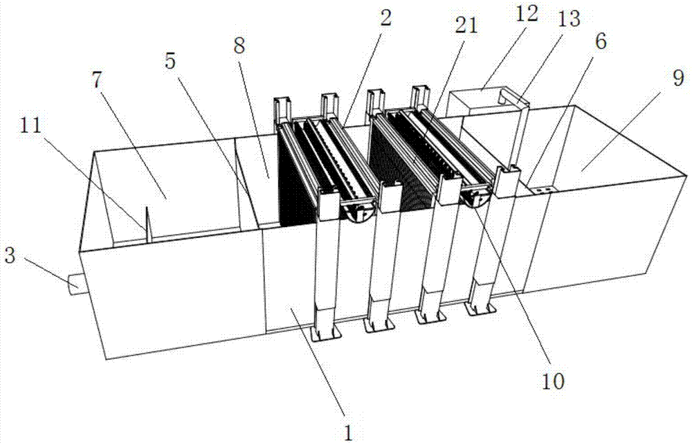
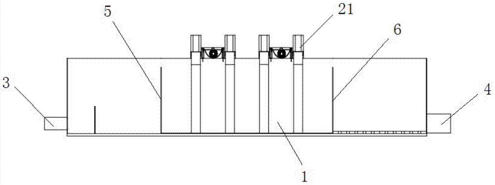
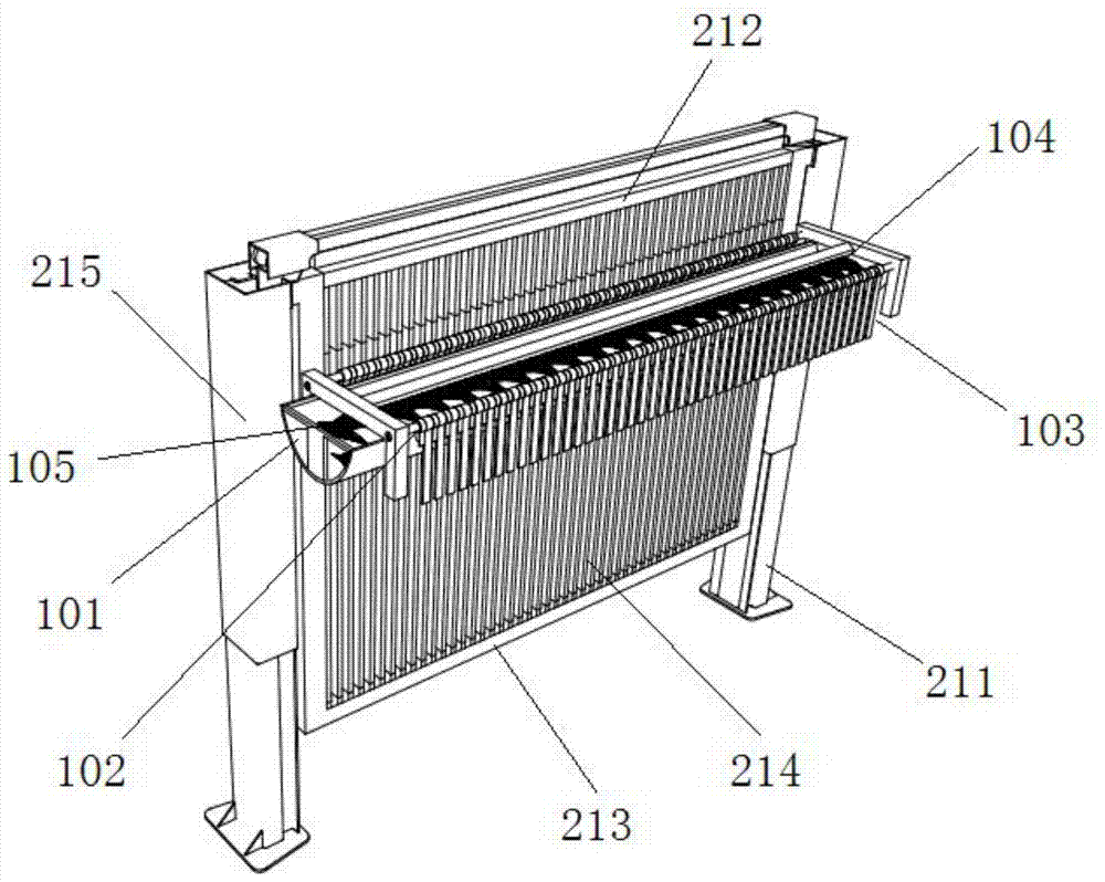
[0031] In this example, see image 3 and Figure 4 A slag removal device 10 for scraping and collecting magnetic slag on the magnetic strip 214 is provided on one side of the magnetic separation grid 21 . The slag removal device 10 is located at the upper part between two adjacent magnetic separation grids 21, and includes a magnetic slag collection tank 101 horizontally arranged on the surface of the movable grid group 212, see figure 1 , the length of the magnetic slag collecting tank 101 is equal to or greater than the width of the magnetic separation cabinet 1, the magnetic slag collecting tank 101 is provided with a scraper shaft 102 on both sides, and the scraper shaft 102 is provided with the same number as the magnetic strip 214, which can be inserted into the adjacent Between the magnetic strips 214, the scraper 103 for scraping off the magnetic slag on the surface of the magnetic strip 214, the magnetic slag collection tank 101 is provided with a cleaning brush 104 ...
Embodiment 2
[0034] In this embodiment, the height of the magnetic separation grid 21 is greater than the height of the magnetic separation cabinet 1 . The purpose is to ensure the installation height of the magnetic strip 214 so that it can complete the adsorption of magnetic slag in a wide range, improve the purification quality, and maximize the water treatment capacity.
Embodiment 3
[0036] In this embodiment, a buffer baffle 11 is provided near the water inlet 3 in the water inlet pool 7 . The purpose is to control the water flow velocity when water is entering, so as to avoid the water flow too fast and have a large impact on the first perforated wall 5, thereby affecting the service life and purification effect of the first perforated wall 5.
PUM
 Abstract
Description
Claims
Application Information
 - R&D Engineer
- R&D Manager
- IP Professional
- Industry Leading Data Capabilities
- Powerful AI technology
- Patent DNA Extraction
Browse by: Latest US Patents, China's latest patents, Technical Efficacy Thesaurus, Application Domain, Technology Topic, Popular Technical Reports.
© 2024 PatSnap. All rights reserved.Legal|Privacy policy|Modern Slavery Act Transparency Statement|Sitemap|About US| Contact US: help@patsnap.com


