Strengthened micro cyclone separator and high-pressure separation device with same

A cyclone separator, a miniature technology, applied in the direction of the swirl flow can reverse the axial direction of the device, the swirl device, etc., can solve the problem of large material consumption and floor space, limited continuous operation time, large gas pressure loss, etc. problem, to achieve the effects of small footprint, improved continuous operation time, and small resistance loss

Inactive Publication Date: 2015-11-18
BEIJING YUANCHENG IND SAFETY TECH CO LTD
View PDF9 Cites 0 Cited by
  • Summary
  • Abstract
  • Description
  • Claims
  • Application Information

AI Technical Summary

Problems solved by technology

This kind of micro cyclone separator has the problems of low separation efficiency and large resistance loss during use. The micro cyclone separator refers to a cyclone separator with a diameter of the upper part of the outer tube ranging from tens to hundreds of millimeters. After the gas-solid-liquid mixed medium enters the micro-cyclone separator, the pressure loss of the gas is large, so it is necessary to set up an additional pressurization device to compensate for the pressure loss to meet the requirements of the gas pressure in the subsequent process
[0003] These problems of the micro cyclone separator of the prior art have seriously affected its application in the gas-liquid or gas-solid-liquid separation device in the industrial field, causing the gas-liquid or gas-solid-liquid separation device to have low separation efficiency, large device volume and lead to material Defects such as large consumption and occupied area, large resistance loss, high energy consumption, and limited continuous operation time

Method used


Image

  • Strengthened micro cyclone separator and high-pressure separation device with same
  • Strengthened micro cyclone separator and high-pressure separation device with same
  • Strengthened micro cyclone separator and high-pressure separation device with same

Examples


Embodiment Construction

[0029] The present invention will be further explained below with reference to specific embodiments and accompanying drawings.

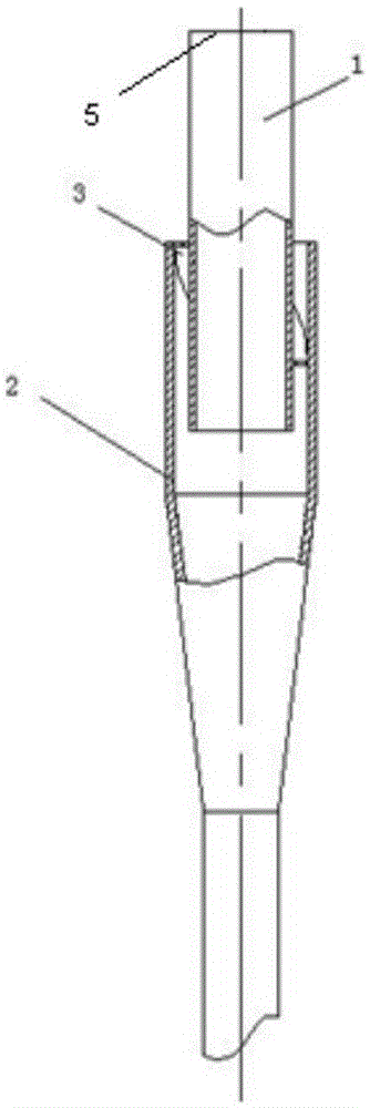
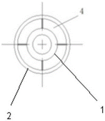
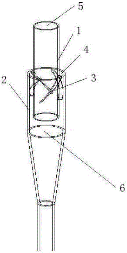
[0030] An enhanced micro-cyclone separator according to an embodiment of the present invention, such as figure 1 As shown, the outer tube 2 and the inner tube 1 are included. The inner pipe 1 is a straight pipe; the outer pipe 2 includes an upper straight pipe part, a middle conical part and a lower straight pipe part with a smaller diameter, and a part of the lower part of the inner pipe 1 enters the upper part of the outer pipe 2 . The top of the inner tube 1 is the gas outlet 5 of the cyclone separator, and guide vanes 3 are arranged between the inner and outer tubes. like figure 2 As shown, the axial opening between the outer tube 2 and the inner tube 1 is the cyclone inlet 4 . In this embodiment, the axial air inlet 4 of the reinforced micro cyclone separator 6 makes the air intake mode axial and increases the air intake area, so as to achie...


PUM


Abstract

The invention discloses a strengthened micro cyclone separator and a high-pressure separation device with the separator. The strengthened micro cyclone separator comprises an outer pipe and an inner pipe. Part of the lower portion of the inner pipe enters the upper portion of the outer pipe. Guiding vanes are arranged between the inner pipe and the outer pipe. An opening between the outer pipe and the inner pipe is a cyclone separator inlet. The outer pipe and the inner pipe are connected through the guiding vanes. The 3-6 guiding vanes are in the spiral line type and are arranged in the circumferential direction of the outer wall of the inner pipe in the same direction and evenly distributed. According to the high-pressure separation device with the separator, a partition plate, the structure, the arrangement mode and the fixing method of the high-pressure cyclone separation device are designed at the same time. The efficient, energy-saving and long-period-running high-pressure separation device is established. Complete separation of gas, liquid and solid in gas, liquid and solid mixtures of the inlet is achieved, and the resistance loss is far smaller than the pressure loss of an existing conventional high-pressure separation device.

Description

technical field [0001] The invention relates to the technical field of gas-liquid or gas-solid-liquid mixture separation, in particular to an enhanced microcyclone separator and its application. Background technique [0002] Currently used micro-cyclone separators for gas-liquid or gas-solid-liquid medium separation all adopt single-port side air intake. Micro-cyclone separators generally include an outer tube and an inner tube, and a part of the lower part of the inner tube enters the upper part of the outer tube , the top of the inner tube is the gas outlet of the cyclone separator, and the top of the outer tube is sealed with the outer wall of the inner tube. The pipe part and the lower straight pipe part with smaller diameter, the air inlet is located on the upper single side of the straight pipe part of the outer pipe. The medium to be separated generally enters from the unilateral inlet of the upper straight pipe part, the separated liquid or liquid-solid mixture is d...

Claims


Application Information

Patent Timeline
Patent Type & Authority Applications(China)
IPC IPC(8): B04C5/103B04C5/28
Inventor 何伯述孙淑园段志鹏
Owner BEIJING YUANCHENG IND SAFETY TECH CO LTD
Why Eureka
Try Eureka