Devices and methods for forming relatively monodisperse droplets
A droplet, adjacent row technology, applied in the field of devices and methods for forming relatively monodisperse droplets, capable of solving problems such as high polydispersity
- Summary
- Abstract
- Description
- Claims
- Application Information
AI Technical Summary
Problems solved by technology
Method used
Image
Examples
Embodiment 1
[0097] Microparticles are ubiquitous in everyday life; they are contained in cosmetic creams, foods, and serve as drug delivery vehicles, among other applications. Microparticles can be collected using a number of different techniques such as spray drying, homogenization, bulk emulsification or membrane filtration. However, control over the size of the particles produced by these techniques is often limited. Because the size of the particles affects their contribution to product properties, limited control over particle size limits the performance of particles produced by these techniques in many applications. In contrast, microfluidics would allow the production of essentially monodisperse particles with close control of their size and composition. Typical frequencies for particle formation in conventional microfluidic devices are 1-10 kHz. Conventional microfluidic devices can be used to produce small volume particles. For products containing particles produced by convent...
Embodiment 2
[0101] This example describes the effect of capillary number on droplet size according to one embodiment of the invention. In this example, it was found that for η 分散 / η 连续 For devices >1, droplet size is relatively dependent on capillary number below capillary number 0.04. Above 2, the droplet size was found to be relatively more dependent on device design (eg, interstitial volume).
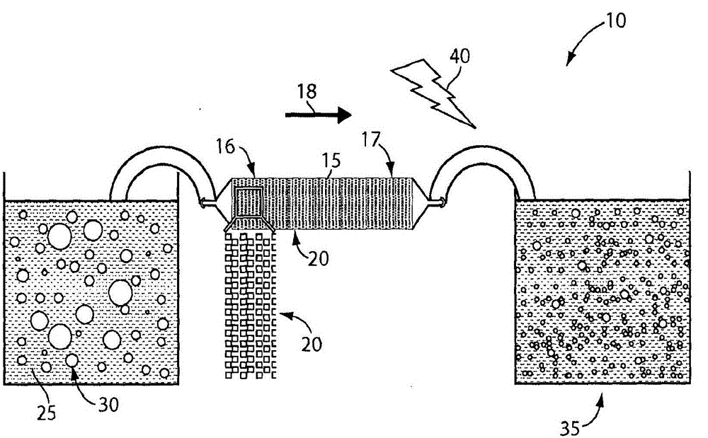
[0102] A schematic illustration of the apparatus and droplet breakup method used in this example can be found in figure 1 . Microfluidic devices were used to produce water-in-oil (W / O) and oil-in-water (O / W) emulsions. Different devices emulsify by mixing two immiscible liquids; the dispersed phase constitutes 60-80 vol%. The continuous phase contains surfactants to prevent coalescence of the droplets. A macroemulsion is formed by mechanically agitating a solution containing two immiscible liquids, and the formed macroemulsion is injected into a microfluidic device. The microfluidic devic...
Embodiment 3
[0110] This example describes the effect of obstacle geometry on droplet breakup and size. Diamond-shaped obstacles, triangular-shaped obstacles, and obstacles with semicircular notches exhibit relatively inefficient droplet splitting, which results in a high coefficient of variation in droplet size. The inefficient droplet breakup was found to be due to poor droplet trapping by obstacles, which reduces the simultaneous squeezing and pushing of droplets to both sides of the obstacle by the incoming fluid. However, some droplet splitting still occurred. Square and circular obstacles exhibit more efficient droplet breakup compared to these shapes, which results in a lower coefficient of variation of droplet size.
[0111] Image 6 Microscopic images of water-in-oil emulsion droplets in outlets of microfluidic devices with different obstacle geometries are shown in . The shapes of the obstacles are illustrated in the inset. All devices used in these experiments were 40 micron...
PUM
| Property | Measurement | Unit |
|---|---|---|
| Average height | aaaaa | aaaaa |
| Average width | aaaaa | aaaaa |
| Diameter | aaaaa | aaaaa |
Abstract
Description
Claims
Application Information
 - R&D
- Intellectual Property
- Life Sciences
- Materials
- Tech Scout
- Unparalleled Data Quality
- Higher Quality Content
- 60% Fewer Hallucinations
Browse by: Latest US Patents, China's latest patents, Technical Efficacy Thesaurus, Application Domain, Technology Topic, Popular Technical Reports.
© 2025 PatSnap. All rights reserved.Legal|Privacy policy|Modern Slavery Act Transparency Statement|Sitemap|About US| Contact US: help@patsnap.com


