Microwave associated imaging radar amplitude-phase error correction method based on auxiliary array elements

An imaging radar, microwave correlation technology, applied in the field of radar, can solve problems such as limitations

Active Publication Date: 2015-11-11
XIDIAN UNIV
View PDF4 Cites 25 Cited by
  • Summary
  • Abstract
  • Description
  • Claims
  • Application Information

AI Technical Summary

Problems solved by technology

In many practical application scenarios, since the amplitude and phase error of the radar array will change with time, temperature and other environmental factors, it is necessary to correct the amplitude and phase error online, and there are great limitations in using the correction source for correction.

Method used


Image

  • Microwave associated imaging radar amplitude-phase error correction method based on auxiliary array elements
  • Microwave associated imaging radar amplitude-phase error correction method based on auxiliary array elements
  • Microwave associated imaging radar amplitude-phase error correction method based on auxiliary array elements

Examples


Embodiment Construction

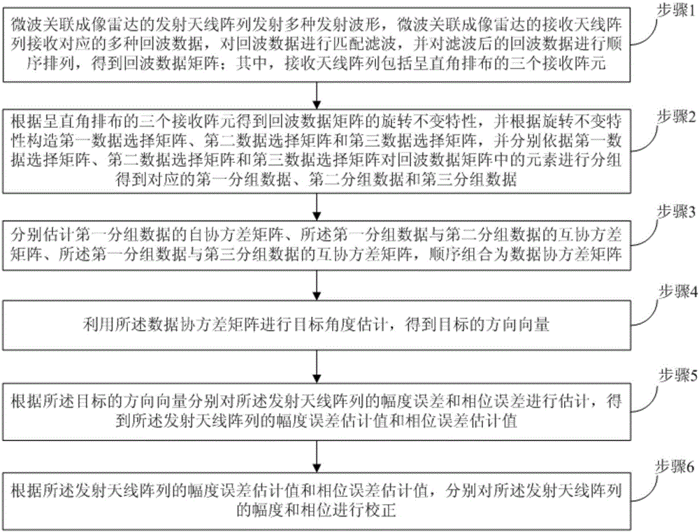
[0101] In order to make the above objects, features and advantages of the present invention more comprehensible, the present invention will be further described in detail below in conjunction with the accompanying drawings and specific embodiments.

[0102] In order to better describe the present invention, firstly, the geometric configuration of the microwave correlation imaging radar used in the present invention will be described. refer to figure 2 , is a schematic diagram of the geometric configuration of the microwave correlation imaging radar used in the present invention. The radar system based on microwave correlation imaging in the present invention includes: receiving array element 1, receiving array element 2, receiving array element 3, transmitting antenna array 4, target 5 and Signal processor 6. The receiving array element 1, the receiving array element 2 and the receiving array element 3 are collectively referred to as auxiliary array elements. Utilize the mi...


PUM


Abstract

The invention provides a microwave associated imaging radar amplitude-phase error correction method based on auxiliary array elements so as to estimate a microwave associated imaging radar amplitude-phase error and then obtain a relatively ideal time and space radiation field by compensation on the amplitude-phase error. The method comprises the steps that step 1: a microwave associated imaging radar transmitting antenna array transmits multiple types of waveforms, corresponding multiple types echo data are received by a receiving antenna array, matched filtering is performed on the echo data, and the obtained echo data matrixes are orderly arranged; step 2: the elements in the echo data matrixes are grouped; step 3: a data covariance matrix is estimated; step 4: target angle estimation is performed so that a target direction vector is obtained; step 5: the amplitude error and the phase error of the transmitting antenna array are estimated respectively so that corresponding error estimation values are obtained; and step 6: the amplitude and the phase of the transmitting antenna array are respectively corrected according to the amplitude error estimation value and the phase error estimation value of the transmitting antenna array.

Description

technical field [0001] The invention belongs to the technical field of radar, in particular to a method for correcting amplitude and phase errors of microwave correlated imaging radars based on auxiliary array elements, which is applied to real-time on-line correction of amplitude and phase errors of correlated imaging radar arrays. Background technique [0002] Radar is an indispensable electronic equipment in modern life. Among them, the microwave correlation imaging radar system can realize staring imaging of the scene, and has broad application prospects in national defense, anti-terrorism, security and other scenes. Because microwave correlation imaging radar needs to transmit different signals in different transmitting elements, it is easier to introduce larger amplitude and phase errors than traditional array radars, and the amplitude and phase errors will continue to change with time, temperature and other environmental factors. When there is an amplitude and phase e...

Claims


Application Information

Patent Timeline
IPC IPC(8): G01S7/40
CPCG01S7/40
Inventor 李军郑煜李小敏廖桂生赵启勇马玉芳
Owner XIDIAN UNIV
Why Eureka
Try Eureka