Power meter for micro motor

A dynamometer and micro-motor technology, applied in the field of micro-motor dynamometer, can solve the problems of difficult to measure motor output power, low work efficiency, etc.

Active Publication Date: 2015-11-11
广州市先河技术工程有限公司
View PDF7 Cites 0 Cited by
  • Summary
  • Abstract
  • Description
  • Claims
  • Application Information

AI Technical Summary

Problems solved by technology

In the prior art, the torque measurement device of the rope pulley method is measured by manually increasing or decreasing weights, and the work efficiency is low. Th

Method used


Image

  • Power meter for micro motor
  • Power meter for micro motor

Examples


Embodiment Construction

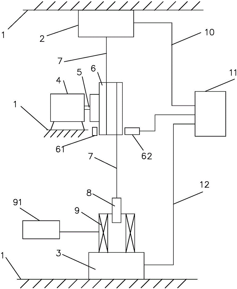
[0023] The structure of the micro-motor dynamometer in the embodiment of the present invention is as follows: figure 1 shown, including:

[0024] - The frame 1 for fixing the motor under test 4, and the motor under test 4 is supported on the mounting platform in the middle of the frame 1;

[0025] - the pulley 6 fixed directly on the shaft end 5 of the motor under test 4 and the wire rope 7 bypassing the pulley 6;

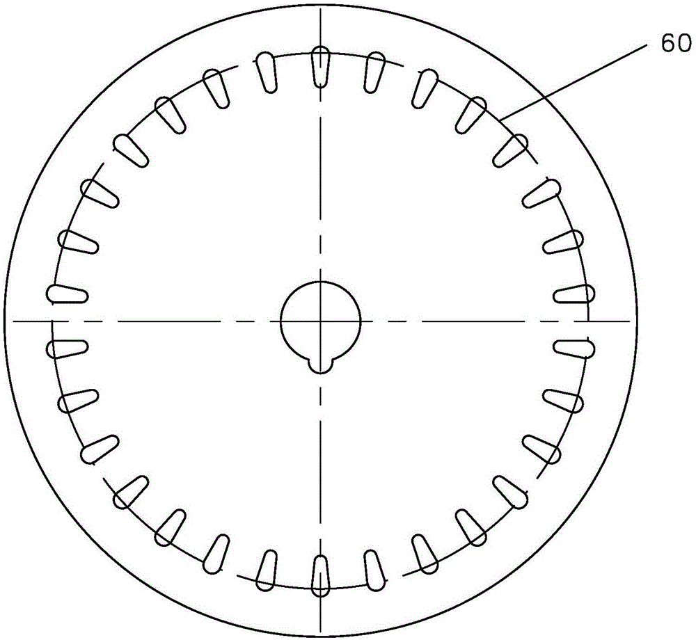
[0026] - pulley 6 as figure 2 As shown, 30 axial through holes of the same size are evenly distributed along the circumference 60 coaxial with it. The light-emitting component 61 and the light-receiving component 62 of the double-molded or shell-inserted photointerrupter are respectively located on the left and right sides of the circumference 60. right two sides;

[0027] ——The shell is fixed on the tension sensor 2 on the top of the frame 1, the force sensing direction is vertically downward, and the upper end of the rope 7 is fixed on the sensing end of the ...


PUM


Abstract

The invention relates to a power meter for a micro motor. The power meter comprises a frame, a pulley, a rope, a rotation speed measuring device, pulling force sensor, an electronic scale, electromagnets and an instrument, wherein the pulley is fixed at the driving end of the motor to be metered, the rope is wound around the pulley, the pulling force sensor is limited in the upper portion of the frame, the force sensing direction of the pulling force sensor is vertically downward, the upper end of the rope is fixed to the sensing end of the pulling force sensor, the electronic scale is supported in the lower portion of the frame, the electromagnets are supported by a weighing disk of the electronic scale, and controlled by an adjustable power supply, the attraction force of the electromagnets is vertically downward, the lower end of the rope is fixed to an armature of the electromagnets, and the instrument receives output signals of the rotation speed measuring device, the pulling force sensor and the electronic scale. A measurement result of the power P of the motor is output according to the equation that P=n(GX+(G0-G)-F)(R+r), n represents to the rotation speed of the metered motor, GX represents the weight of the armature, G0 represents the weight, weighed by the electronic scale, of the electromagnets before electrification, G represents the weight, weighed by the electronic scale, of the electromagnets when being electrified in set voltage, F represents the pulling force measured by the pulling force sensor, R represents the radius of the pulley, and r represents the radius of the rope. The power meter can be used to measure the output power of the micro motor automatically.

Description

technical field [0001] The invention relates to a micro-motor dynamometer, in particular to its loading device and control, which can belong to G01L3 / 00 in the international patent classification table. Background technique [0002] The national industry standard JB / T9544 "Test Methods for Small Power Synchronous Motors" provides a torque measurement method for tiny motors with a shaft power of less than a few watts - the rope pulley method. The torque measurement device of the prior art rope pulley method is measured by manually increasing or decreasing weights, which has low working efficiency and therefore the measured torque characteristic can only be intermittent, and it is difficult to directly obtain the output power of the motor under test instantaneously. Contents of the invention [0003] The technical problem to be solved by the present invention is to propose a micro-motor dynamometer, which can improve the existing problems of the prior art. [0004] The tech...

Claims


Application Information

Patent Timeline
IPC IPC(8): G01L3/24
Inventor 叶露微
Owner 广州市先河技术工程有限公司
Why Eureka
Try Eureka