
A spring air pressure damping shock absorber

A shock absorber and air pressure technology, which is applied in the direction of spring/shock absorber, shock absorber, gas shock absorber, etc., can solve the problems of poor air pressure damping resilience and soft shock absorber, so as to increase the load and realize Soft and hard balance, moderate rebound effect

Inactive Publication Date: 2017-03-01
常州市达文电动车辆配件厂
View PDF8 Cites 0 Cited by
  • Summary
  • Abstract
  • Description
  • Claims
  • Application Information

AI Technical Summary

Problems solved by technology

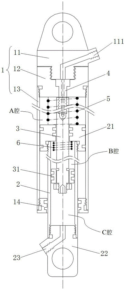
[0005] The object of the present invention is to overcome the above-mentioned deficiencies of the existing shock absorbers, and provide a spring air pressure damping shock absorber. By adopting the technical solution of the present invention, the elastic force of the damping spring is used to improve the problem of insufficient resilience of the air pressure damping, and the damping spring and The gas damping is organically combined. When the shock absorber is pressed down, the damping spring can assist the air pressure damping to provide shock absorption, increase the load of the shock absorber, and overcome the softness of the air pressure damping shock absorber. When the shock absorber rebounds, The damping spring promotes the rebound of the shock absorber, which improves the problem of poor air pressure damping resilience, and under the action of air pressure damping force, the damping spring is softer, which eliminates the self-vibration phenomenon of the spring and makes the shock absorber moderate in resilience , to achieve the soft and hard balance of the shock absorber, thereby improving the shock absorption effect

Method used


Image

  • A spring air pressure damping shock absorber
  • A spring air pressure damping shock absorber
  • A spring air pressure damping shock absorber

Examples


Embodiment 1

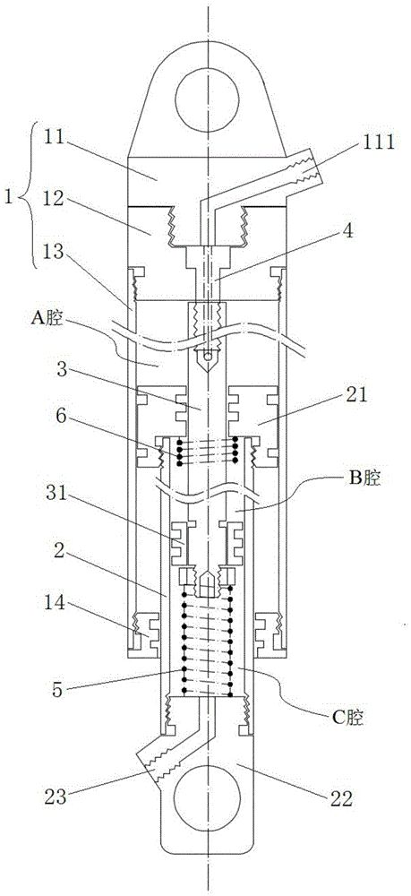
[0030] combine figure 1 and figure 2 As shown, a spring air pressure damping shock absorber of this embodiment mainly includes an outer tube 1, an inner tube 2 and a piston rod 3, the inner tube 2 is arranged inside the outer tube 1, one end is located inside the outer tube 1, and the other end Located outside the outer tube 1, and the end of the inner tube 2 located inside the outer tube 1 is provided with an inner tube piston 21, which cooperates with the inner wall of the outer tube 1 to form a sealed cavity A; one end of the piston rod 3 is fixed on the The end of the outer tube 1, the other end passes through the inner tube piston 21 and extends into the sealed inner tube 2, and at this end is provided with a damping piston 31 that matches the inner wall of the inner tube 2, and the damping piston 31 separates the inner tube 2 It is a sealed chamber B and C chamber, wherein, chamber B is a chamber with a rod, chamber C is a chamber without a rod; chamber A, chamber B an...

Embodiment 2

[0034] The basic structure of a spring air pressure damping shock absorber of this embodiment is the same as that of Embodiment 1, the difference is that: the damping piston 31 in this embodiment is also provided with air pressure damping holes, and the damping of the damping piston 31 by the gas medium is used. The damping effect in the hole greatly improves the damping force of the gas medium, making the air pressure damping effect more stable. The structure of the above-mentioned damping piston 31 and the Chinese patent number: ZL201520070094.X, the authorized announcement date is: July 1, 2015, and the name of the invention is: a pneumatic damping mechanism and a pneumatic damping shock absorber using the mechanism, published in The structure and principle of the damping piston are the same, and will not be repeated here.

Embodiment 3

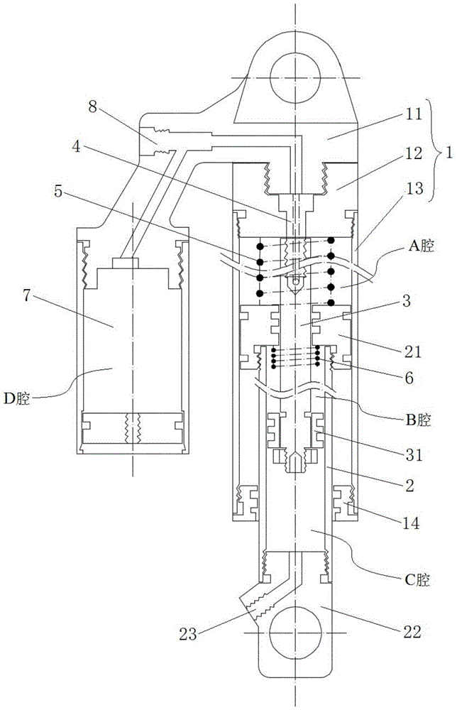
[0036] combine image 3 and Figure 4 As shown, the basic structure of a kind of spring air pressure damping shock absorber of the present embodiment is the same as that of Embodiment 1, the difference is that: the outer tube 1 of the present embodiment is provided with a pressure bottle 7 communicating with the A cavity, and the outer tube 1 includes The upper shaft base 11, the connecting piece 12 and the hollow sleeve 13, the upper shaft base 11 is connected with the hollow sleeve 13 through the connecting piece 12, the piston rod 3 is fixedly installed on the connecting piece 12 by the lifting screw 4, and the lifting screw 4 A vent hole is provided, and the air pressure bottle 7 is arranged on the side wall of the upper shaft seat 11, and the air pressure bottle 7 communicates with the A cavity through the above-mentioned vent hole; The damping adjustment rod 8 and the air pressure bottle 7 are equivalent to the D cavity, and the air pressure bottle 7 can automatically r...


PUM


Abstract

The invention discloses a spring air pressure damping shock absorber and belongs to the field of shock absorbers. The shock absorber comprises an outer pipe, an inner pipe and a piston rod, the inner pipe is arranged inside the outer pipe, the end, located inside the outer pipe, of the inner pipe is provided with an inner pipe piston, and the inner piston cooperates with the inner wall of the outer pipe for forming a sealed cavity A; one end of the piston rod is fixed at the end of the outer pipe, the other end of the piston rod passes through the inner pipe piston and extends into the sealed inner pipe, a damping piston matched with the inner wall of the inner pipe is arranged at the other end of the piston rod, and the inner pipe is divided into a cavity B and a cavity C through the damping piston; the cavity A, the cavity B and the cavity C are all filled with gas, a damping spring is arranged inside the cavity A or the cavity C, and the load born by the damping spring is from one thirds to a half of that born by the shock absorber. According to the shock absorber, by utilizing the elastic force of the damping spring, the problem that the air pressure damping is insufficient in rebound resilience is improved, the damping spring and the air damping are combined organically, the rebound resilience of the shock absorber is made to be moderate, the balance between hardness and softness of the shock abosrber is achieved, and therefore the shock absorption effect is improved.

Description

technical field [0001] The present invention relates to a kind of shock absorber, relate to a kind of spring air pressure damping shock absorber more specifically, can be used for the front and rear shock absorption of bicycle, electric vehicle (including two-wheel, three-wheel, four-wheel) and motorcycle use. Background technique [0002] The shock absorber installed on the motorcycle can alleviate and attenuate the impact and vibration of the motorcycle due to the unevenness of the road during driving, ensure the smoothness and comfort of driving, and help improve the service life of the motorcycle and the stability of the operation sex. Existing motorcycle shock absorbers can be roughly divided into spring shock absorbers, spring-air damping shock absorbers, hydraulic damping shock absorbers, and oil-air combined front fork shock absorbers according to the working medium. and nitrogen-filled hydraulic shock absorbers, etc. [0003] The existing spring-type shock absorb...

Claims


Application Information

Patent Timeline
Patent Type & Authority Patents(China)
IPC IPC(8): F16F13/00F16F9/02F16F9/32
CPCF16F9/02F16F9/0209F16F9/32F16F13/00
Inventor 许伟
Owner 常州市达文电动车辆配件厂
Learn More