
Gasket transferring mechanism

A gasket and moving plate technology, which is applied in the direction of conveyors, conveyor objects, vibrating conveyors, etc., can solve the problems that gaskets cannot move in multiple ways, and achieve the effect of multi-directional movement

Active Publication Date: 2015-11-11
南通如港船舶配套机械有限公司
View PDF6 Cites 2 Cited by
  • Summary
  • Abstract
  • Description
  • Claims
  • Application Information

AI Technical Summary

Problems solved by technology

[0002] The current shim transfer mechanism cannot realize the multi-way movement of the shim

Method used


Image

  • Gasket transferring mechanism

Examples


Embodiment Construction

[0013] The present invention will be further described below in conjunction with the accompanying drawings and specific embodiments.

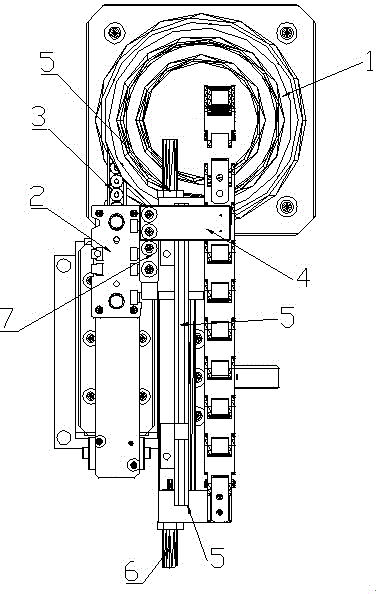
[0014] according to figure 1 , the gasket transplanting mechanism, including the gasket feeding vibrating plate 1, realizes that the gasket moves in the feeding groove through vibration, and it is characterized in that the gasket feeding vibrating disk is connected with the first feeding groove 3 and the second feeding groove 7 at the same time; The first feeding chute is provided with a cover plate 2 for preventing dust; the second feeding chute is covered with a push plate 4, and a movable plate 5 is arranged below the push plate, and the movable plate It is not connected with the second feeding chute.

[0015] The movable plate and the push plate are arranged perpendicular to each other, and the movable plate can be moved until the part of the movable plate is located below the push plate or the entire movable plate is away from the push pl...


PUM


Abstract

The invention relates to the field of moving mechanisms, in particular to a gasket transferring mechanism. The gasket transferring mechanism comprises a gasket feeding vibration disc and is characterized in that the gasket feeding vibration disc is connected with a first feeding groove and a second feeding groove at the same time; a cover plate is arranged on the first feeding groove; a pushing plate covers the second feeding groove; a movable plate is arranged below the pushing plate. The gasket transferring mechanism has the beneficial effect that multi-directional movement of gaskets is achieved.

Description

technical field [0001] The invention relates to the field of moving mechanisms, in particular to a gasket transplanting mechanism. Background technique [0002] The current shim transfer mechanism cannot realize the multi-mode movement of the shim. Contents of the invention [0003] The purpose of the present invention is to overcome the above problems and provide a shim transplanting mechanism that realizes multi-directional movement of shims. [0004] In order to achieve the above object, the technical solution adopted in the present invention is: a gasket transplanting mechanism, including a gasket feeding vibrating plate, characterized in that the gasket feeding vibrating plate is connected with the first feeding trough and the second feeding trough at the same time; The first feeding chute is provided with a cover plate, the second feeding chute is covered with a push plate, and a movable plate is arranged under the push plate. [0005] In the aforementioned spa...

Claims


Application Information

Patent Timeline
Patent Type & Authority Applications(China)
IPC IPC(8): B65G27/00B65G47/82
Inventor 尹太阳
Owner 南通如港船舶配套机械有限公司
Learn More