
Rapid thermometer and its temperature measurement control method

A thermometer and fast technology, applied in the directions of diagnostic recording/measurement, medical science, diagnosis, etc., which can solve the problems of difficulty in ensuring the accuracy of temperature measurement results, affecting measurement results, and long measurement time.

Active Publication Date: 2018-12-11
HETAIDA TECH CO LTD
View PDF5 Cites 0 Cited by
  • Summary
  • Abstract
  • Description
  • Claims
  • Application Information

AI Technical Summary

Problems solved by technology

[0002] At present, the thermometer conducts external heat transfer completely through the temperature, so that the temperature of the thermometer rises to the real temperature of the measured object; for example: human body temperature measurement, which uses a thermometer to directly contact the human body for external heat transfer. The measurement time is long (generally about 5 minutes), therefore, the user needs to spend a long time waiting for the temperature measurement item, and also wastes the doctor's medical consultation time; especially, the long measurement time causes the measured object to It is more difficult to maintain an accurate measurement posture / method all the time, which may affect the measurement results, and it is difficult to ensure the accuracy of the temperature measurement results. For objects such as crying babies, this problem is more obvious

Method used


Image

  • Rapid thermometer and its temperature measurement control method
  • Rapid thermometer and its temperature measurement control method
  • Rapid thermometer and its temperature measurement control method

Examples


Embodiment Construction

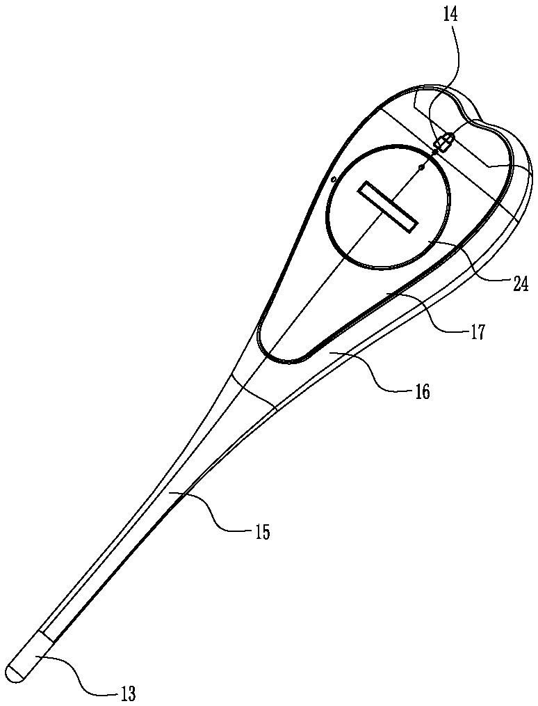
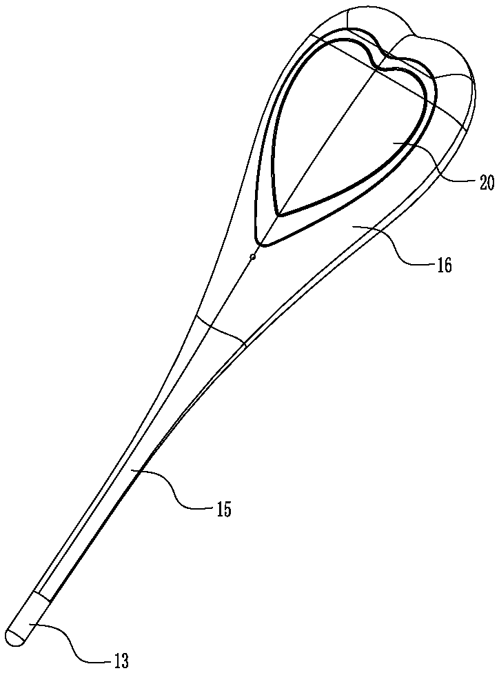
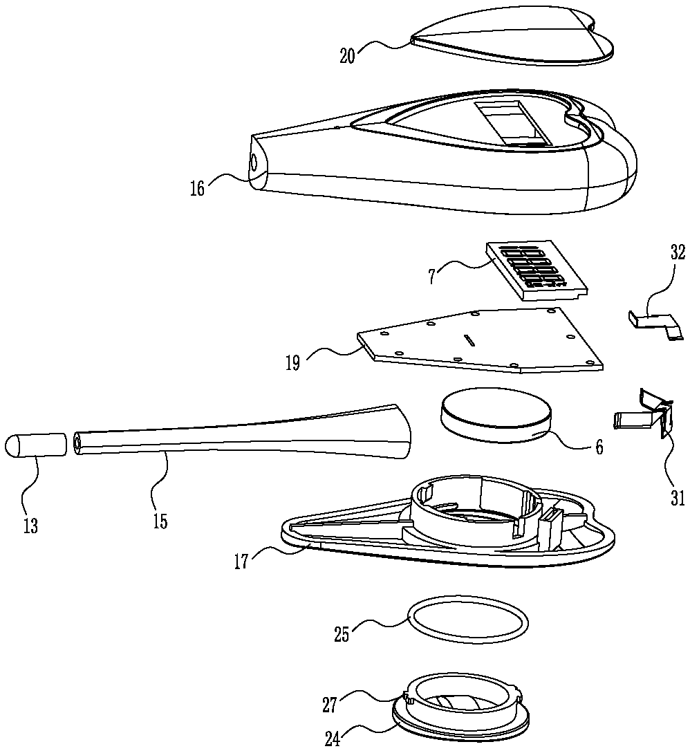
[0044] Please refer to Figure 1 to Figure 7 As shown, it has shown the specific structure of the embodiment of the present invention, this kind of fast thermometer includes shell, probe head 13, main control unit 1 (for example: MCU), heating unit 2 (for example: heating wire), A heating control unit 3 , a temperature sensing element 4 , a temperature detection unit 5 , a power supply 6 , a display unit 7 and a switch 14 .

[0045] Wherein, the probe head 13 and the heating unit 2 transfer heat to the temperature sensing element 4, and the temperature sensing element 4 is preferably designed as an NTC thermistor (that is, a negative temperature coefficient thermistor). Of course, other suitable temperature sensors can also be selected. , here, without any limitation; the temperature sensing element 4 is connected to the temperature detection unit 5, and the temperature detection unit 5 feeds back the temperature signal to the main control unit 1; the main control unit 1 is co...


PUM


Abstract

The invention discloses a rapid temperature measuring instrument and a temperature measuring control method thereof, wherein the rapid temperature measuring instrument comprises an outer shell, a probe head, a main control unit, a heating unit, a heating control unit, a temperature-sensing element, a temperature detecting unit, a power source, a display unit and a switch; when the temperature is needed to be measured, the switch isswitched on; the main control unit is used to start the heating unit through the heating control unit to produce heat; the heat is transferred to the temperature-sensing element and at the same time, the probe head is used to synchronously transfer the heat of an object to be measured to the temperature-sensing element; when the temperature sensed by the temperature detecting unit reaches at the set pre-heating temperature value, the main control unit will stop the work of the heating unit through the heating control unit; the rest of the work will be finished by the probe head only, that is to say, the contact heat of the object to be measured is transferred only by the probe head until the contact heat reaches at the actual temperature; and the detected temperature value is displayed directly by the display unit, thus the time of measuring the temperature is greatly shortened; the time of a user and the time of medical diagnosis by a doctor are saved; and the rapid temperature measuring instrument is suitable for popularizing at sites such as household, clinics and hospitals.

Description

technical field [0001] The invention relates to the technology in the field of temperature measurement, in particular to a rapid thermometer and a temperature measurement control method thereof. Background technique [0002] At present, the thermometer conducts external heat transfer completely through the temperature, so that the temperature of the thermometer rises to the real temperature of the measured object; for example: human body temperature measurement, which uses a thermometer to directly contact the human body for external heat transfer. The measurement time is long (generally about 5 minutes), therefore, the user needs to spend a long time waiting for the temperature measurement item, and also wastes the doctor's medical consultation time; especially, the long measurement time causes the measured object to It is more difficult to maintain an accurate measurement posture / method all the time, which may affect the measurement results, and it is difficult to ensure t...

Claims


Application Information

Patent Timeline
Patent Type & Authority Patents(China)
IPC IPC(8): A61B5/01
Inventor 陈振光
Owner HETAIDA TECH CO LTD
Learn More