
Combustion cylinder piston locking rebound device of split internal combustion engine

A split-type internal combustion engine and combustion cylinder technology, applied in mechanical equipment, engine components, machines/engines, etc., can solve the problems of high engine combustion chamber temperature, high combustion cylinder pressure, increase compression ratio, etc., to ensure stable operation and response. Timely, unlocking force reduction effect

Active Publication Date: 2015-11-04
海门名驰工业设计有限公司
View PDF6 Cites 0 Cited by
  • Summary
  • Abstract
  • Description
  • Claims
  • Application Information

AI Technical Summary

Problems solved by technology

[0002] Increasing the compression ratio of the internal combustion engine can increase the output power of the internal combustion engine, but as the air is compressed, the air temperature will rise, the greater the pressure, the greater the temperature rise, and when the compression is large, the temperature of the supercharged gas will also be very high High, high-temperature compressed air enters the combustion chamber, which can easily cause the engine combustion room to be too high, causing knocking and other failures, so it is difficult to further increase the compression ratio
For example, CN103967587A discloses a split-cylinder type two-stage compression engine, which divides gas compression and work into two parts to complete, which solves the problem of excessive compression ratio, but the pressure in the combustion cylinder is very large in the actual process, which will It will cause great damage to the piston. The impact of multi-piston can be reduced by adopting the method of graded piston, but this method needs to periodically control the start and stop of the high-pressure piston

Method used


Image

  • Combustion cylinder piston locking rebound device of split internal combustion engine

Examples


Embodiment Construction

[0020] The following specific examples are only explanations of the present invention, and it is not a limitation of the present invention. Those skilled in the art can make modifications without creative contribution to the present embodiment as required after reading this specification, but as long as they are within the rights of the present invention All claims are protected by patent law.

[0021] The present invention will be described in detail below with reference to the accompanying drawings.

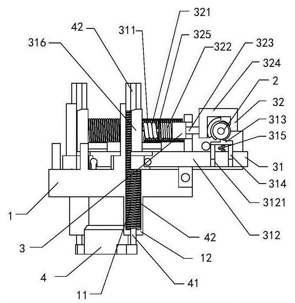
[0022] According to reference figure 1 As shown, a split-type internal combustion engine combustion cylinder piston locking and rebounding device includes: a working cylinder head 1, a camshaft 2 located above the working cylinder head 1, a locking and rebounding device 3 connected to the camshaft 2, a penetrating The piston 4 of the working cylinder cylinder head 1 and the camshaft 2 are used to control the locking rebound device 3, thereby controlling the position of the pis...


PUM


Abstract

The invention relates to an internal combustion engine piston control system, in particular to a combustion cylinder piston locking rebound device of a split internal combustion engine. The device comprises a work cylinder cover, a cam shaft located on the work cylinder cover, a locking rebound device body connected with the cam shaft, and a piston penetrating through the work cylinder cover. The locking rebound device body is located on the work cylinder cover and comprises a locking part and an unlocking part, wherein the locking part is directly located on the upper surface of the work cylinder cover, and the unlocking part is located on the locking part. A piston connection rod is arranged on the two sides of the piston. The piston connection rod is sleeved with a piston rebound spring, and a connection rod cap is arranged on the top of the piston connection rod. The device is good in locking and unlocking effect, responses are timely, the device and other mechanisms of the internal combustion engine can be kept in a common control frequency, and stable operation of the internal combustion engine is guaranteed. Besides, two unlocking springs are arranged, required unlocking force is reduced, energy consumption is smaller, and the use effect is good.

Description

technical field [0001] The invention relates to a piston control system of an internal combustion engine, in particular to a split type internal combustion engine combustion cylinder piston locking rebound device. Background technique [0002] The output power of the internal combustion engine can be increased by increasing the compression ratio of the internal combustion engine, but as the air is compressed, the air temperature will rise, the greater the pressure, the greater the temperature rise, and when the compression is large, the temperature of the supercharged gas will also be very high High, high-temperature compressed air enters the combustion chamber, which can easily cause the engine combustion room to be too high, causing knocking and other failures, so it is difficult to further increase the compression ratio. For example, CN103967587A discloses a split-cylinder type two-stage compression engine, which divides gas compression and work into two parts to complete...

Claims


Application Information

Patent Timeline
Patent Type & Authority Applications(China)
IPC IPC(8): F02B77/00
Inventor 徐树成
Owner 海门名驰工业设计有限公司
Learn More