Steady portable combined type lifting equipment and use method thereof
A combined and portable technology, applied in the direction of lifting devices, etc., can solve the problems of inflexible use of mechanical jacks, inability to meet the needs of use, and high energy consumption of the transmitted force, so as to facilitate on-site assembly, take up no space, and facilitate replacement of parts Effect
- Summary
- Abstract
- Description
- Claims
- Application Information
AI Technical Summary
Problems solved by technology
Method used
Image
Examples
Embodiment 1
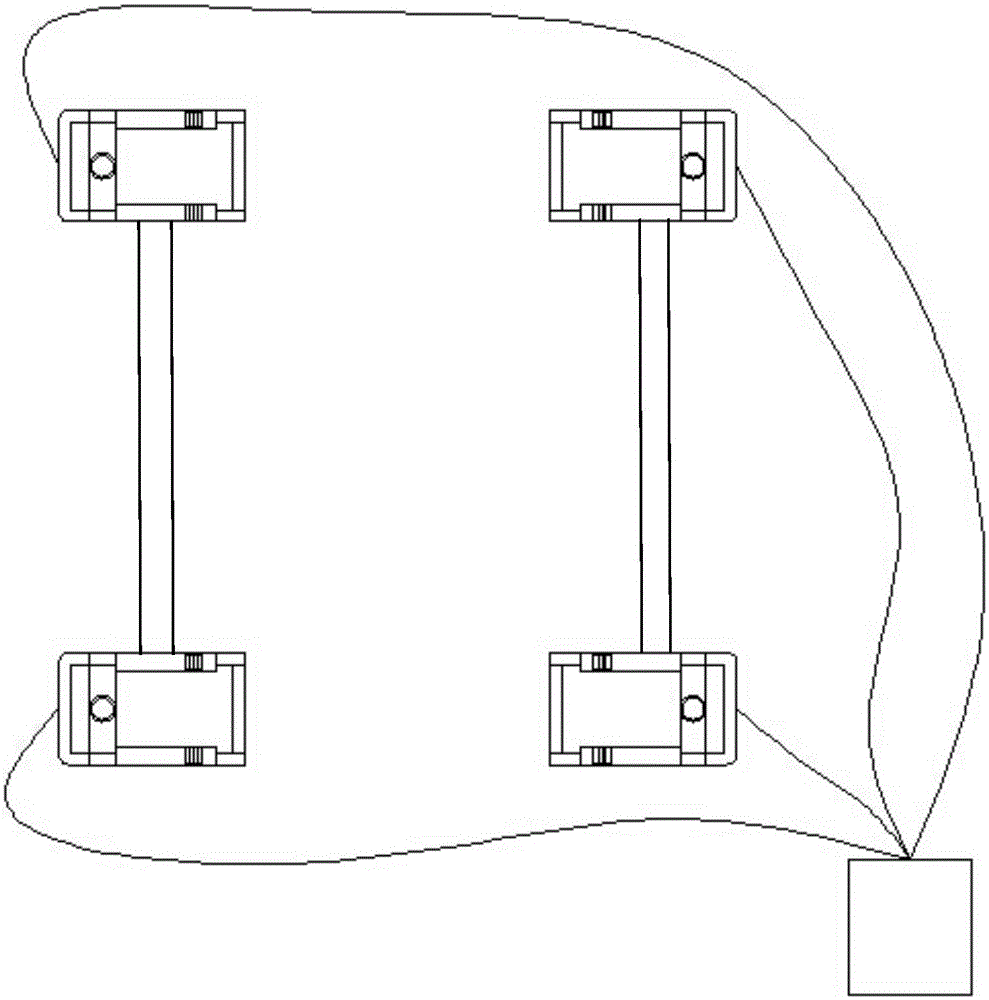
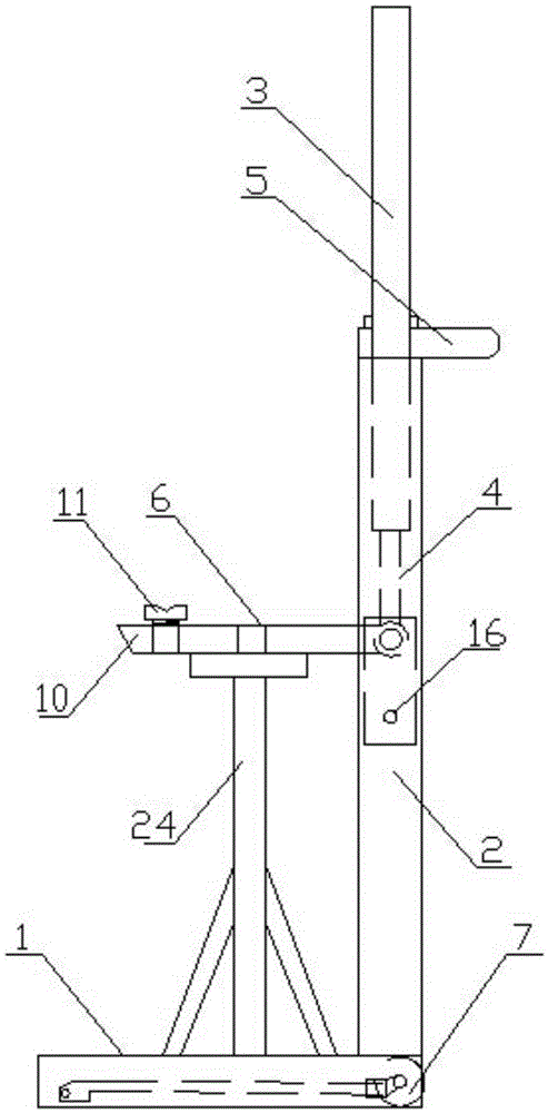
[0037] Such as Figure 9 , Figure 10As shown, the fixed part is a pin, the bottom of the pin is vertically fixed on the support leg of the lift, the top of the pin is fixed with a semicircular pressure cap, and one end of the connecting rod is provided with a through hole, which can be Accommodate the pin cylinder to pass through, the semicircular pressure cap on the top of the pin cylinder is stuck outside the side wall of the connecting rod, the locking part is a fixed plate with a hole, and the bottom of the fixed plate is vertically fixed on the lift On the supporting legs of the machine, there are two raised horizontal plates at the other end of the connecting rod, and there are fixing holes on the horizontal plates. The fixing plate of the locking part can be inserted into the middle of the two horizontal plates, and penetrate into the holes through pins or bolts. Fix the connecting rod and the locking part.
[0038] When in use, rotate the connecting plate so that th...
Embodiment 2
[0040] Such as Figure 11 As shown, the fixed part is a three-way cylindrical bushing, the main pipe of the cylindrical bushing is socketed on the mast of the lift, and fixed on the mast of the lift through an inner bearing. Fixed, the fixed part can be rotated around the axis of the mast, and it can play a role in fine-tuning when connecting two lifts, reducing the stress on the connecting rod and increasing flexibility. The secondary tube of the cylindrical sleeve passes through the inner bearing and the connecting rod One end of the connecting rod is fixed so that the connecting rod can rotate around the horizontal axis to prevent deformation caused by torque during the connection process; the locking part is a ring fixed on the lift mast, the position is equal to the fixed part, and the side of the ring A horizontal cylindrical tube is fixed on the wall, and the end of the cylindrical tube is provided with an external thread; the outer wall of the other end of the connecti...
Embodiment 3
[0042] Such as Figure 12 , Figure 13 As shown, the fixed part is a three-way cylindrical casing, the main pipe of the cylindrical casing is fixed on the mast of the lift through the inner bearing, and the secondary pipe of the cylindrical casing is connected with the Y-shaped connector through the inner bearing. The Y-shaped connector is fixed to one end of the connecting rod through bolts or pins, and the Y-shaped connector can be used to lift or drop the connecting rod in the vertical direction for easy storage; the locking part is fixed on the lift mast The ring is positioned at the same height as the fixed part, and a raised U-shaped groove is fixed on the side wall of the ring, and a powerful magnet is fixed on the inner wall of the groove, and a symmetrical L-shaped card slot is also arranged on the bottom side wall of the U-shaped groove , a strong magnet is used in the groove, which can play a positioning role. When putting the connecting rod, it can be more quickly...
PUM
 Abstract
Description
Claims
Application Information
 - R&D
- Intellectual Property
- Life Sciences
- Materials
- Tech Scout
- Unparalleled Data Quality
- Higher Quality Content
- 60% Fewer Hallucinations
Browse by: Latest US Patents, China's latest patents, Technical Efficacy Thesaurus, Application Domain, Technology Topic, Popular Technical Reports.
© 2025 PatSnap. All rights reserved.Legal|Privacy policy|Modern Slavery Act Transparency Statement|Sitemap|About US| Contact US: help@patsnap.com


