Reprocessing traction device

A traction device and frame technology, applied in the direction of hoisting device, spring mechanism, etc., can solve the problems of low efficiency and high labor intensity, and achieve the effect of reducing labor intensity and improving production efficiency

Inactive Publication Date: 2015-11-04
湖南省柳源机械设备有限公司
View PDF0 Cites 0 Cited by
  • Summary
  • Abstract
  • Description
  • Claims
  • Application Information

AI Technical Summary

Problems solved by technology

[0002] The driving wheel shaft of the traditional car return traction device is installed in the box, and the driven wheel shaft is welded in the box. The installation method is to open U-shaped grooves and punch holes for installation. After the driven wheel shaft is installed, it needs to be welded. When maintenance is required, Since the equipment is installed in the pit, it needs to be hoisted out by driving first, and then the welded part is cut and disassembled by knocking, which is labor-intensive and inefficient

Method used


Image

  • Reprocessing traction device
  • Reprocessing traction device
  • Reprocessing traction device

Examples


Embodiment Construction

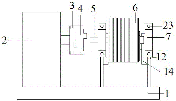
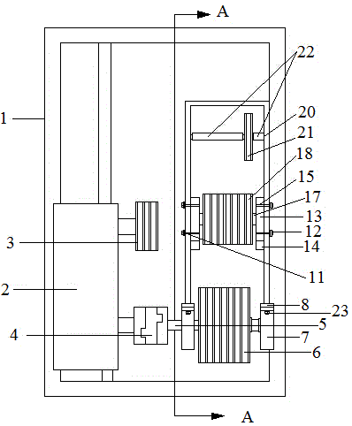
[0012] exist Figure 1 to Figure 4 Among them, this carriage return traction device includes a frame 1, which is characterized in that a reducer 2 is installed on the left side of the frame 1, a first pulley 3 is provided on the right side of the front part of the reducer 2, and a power is provided on the right side of the rear part of the reducer 2. The output shaft 3 and the power output shaft 3 are connected with the driving steel rope wheel shaft 5 through the cross coupling 4, the driving steel cable wheel shaft 5 is connected with the driving steel cable wheel 6 through a key, and the driving steel cable wheel shaft 5 has a bearing housing 7 with bearings The first iron block 8 is welded on the frame 1 on both sides of the active steel rope wheel 6, and there are two first through holes 9 on the first iron block 8, and there is a square concave hole at the connection between the first iron block 8 and the frame 1. Groove 10, the bearing housing 7 with bearing is vertical...


PUM


Abstract

A reprocessing traction device comprises a rack and is characterized in that a speed reducer is mounted on the left side of the rack, a first belt wheel is arranged on the right side of the front of the speed reducer, a power output shaft is arranged on the right side of the rear of the speed reducer, the power output shaft is connected with an active steel rope wheel shaft through a cross coupling, the active steel rope wheel shaft is connected with a driving wheel through a key, a bearing pedestal with a bearing is arranged on the active steel rope wheel shaft, first iron blocks are welded on the rack on the two sides of an active steel rope wheel, two first through holes are formed in the first iron blocks, square grooves are formed in the connecting parts of the first iron blocks and the rack, the bearing pedestal with the bearing is perpendicularly mounted on the first iron blocks through first bolts, four second through holes are formed in two side plates in the middle of the right side of the rack, and second iron blocks are mounted in the second through holes through second bolts. The reprocessing traction device has the advantages that the labor intensity is reduced, and the production efficiency is improved. Originally, workers need to spend seven hours on disassembling the driving wheel and a driven wheel and feel very tired. Now, only one hour is required, and the workers feel very easy.

Description

technical field [0001] The invention relates to a transport device for a brick factory or a tunnel kiln car, in particular to a carriage return traction device. Background technique [0002] The driving wheel shaft of the traditional car return traction device is installed in the box, and the driven wheel shaft is welded in the box. The installation method is to open U-shaped grooves and punch holes. Since the equipment is installed in the pit, it needs to be hoisted out with a crane first, and then the welded part is cut and disassembled by knocking, which is labor-intensive and inefficient. Contents of the invention [0003] In order to reduce labor intensity and improve production efficiency, the invention proposes a carriage returning traction device. [0004] This carriage return traction device includes a frame, which is characterized in that a reducer is installed on the left side of the frame, a first pulley is arranged on the right side of the front part of the r...

Claims


Application Information

Patent Timeline
Patent Type & Authority Applications(China)
IPC IPC(8): B66D1/26B66D1/14B66D1/30
CPCB66D1/26B66D1/14B66D1/30
Inventor 熊双民
Owner 湖南省柳源机械设备有限公司
Why Eureka
Try Eureka