Rack elevator and loading mechanism

A loading mechanism and lifting device technology, applied in storage devices, transportation and packaging, adjustable cabinets, etc., can solve the problems of increasing the overall size and manufacturing difficulty, high processing costs of coil springs, and difficult layout of buffer devices. To achieve the effects of compact structure, easy manufacture, and expanded load range

Inactive Publication Date: 2004-11-17
广州市铭珈智能家居有限公司
View PDF1 Cites 0 Cited by
  • Summary
  • Abstract
  • Description
  • Claims
  • Application Information

AI Technical Summary

Problems solved by technology

Due to the high processing cost and large space occupied by the coil spring, it is difficult to arrange the buffer device, so the overall size and manufacturing difficulty are increased, and the cost is also high

Method used


Image

  • Rack elevator and loading mechanism
  • Rack elevator and loading mechanism
  • Rack elevator and loading mechanism

Examples


Embodiment Construction

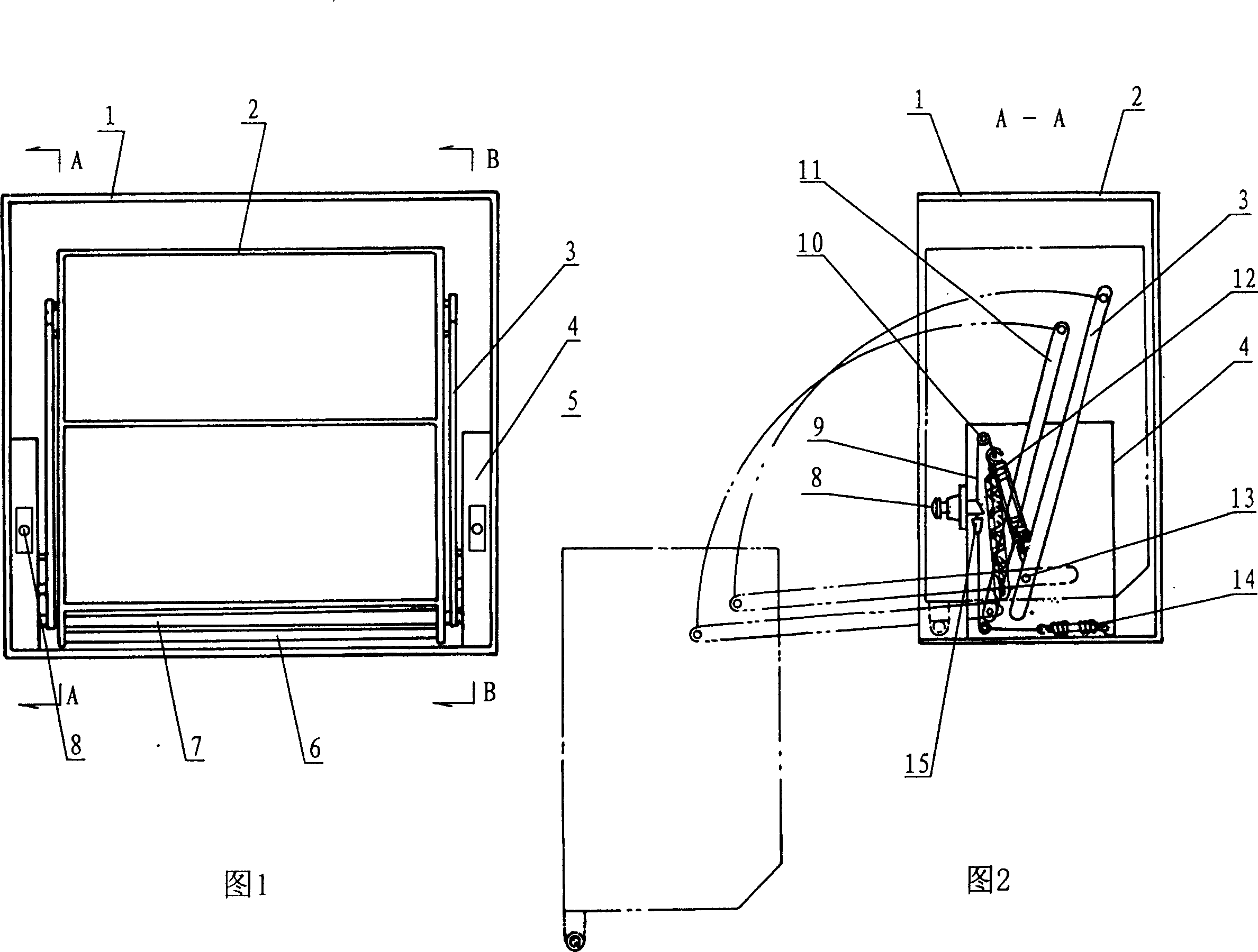
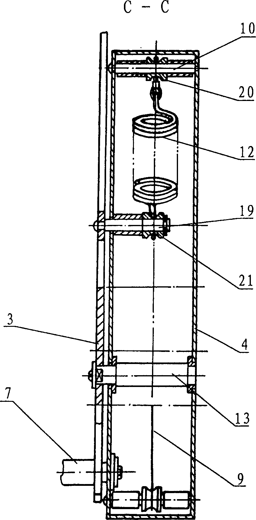
[0018] The specific structure of the present invention will be described in detail according to Figs. 1-6. This device is improved on the basis of the structure of the original "storage rack lifting device", except that the locker 1 in the original device and the storage rack 2 assembled in it and the left and right active connecting Xuan 3 and the left and right Outside the basic structure of components such as driven link 11 and left and right lift controllers, in its left and right lift controller housings 4, a backup accumulator 12 for loading is respectively set. The balance force and energy storage capacity of the two backup energy storage devices 12 can be the same or different. They can be loaded separately or simultaneously. The structure of the backup energy storage device 12 can be a tension spring according to actual needs; a pneumatic cylinder or other energy storage damping buffer device can also be selected. In this embodiment, the backup energy storage device...


PUM


Abstract

The present invention includes storing cupboard, racks inside the cupboard, right and left driving links and driven links and right and left elevation controller. Technologically, the main points include energy accumulators assembled inside the casing of elevation controllers and each energy accumulator has one end hinged to the fixing shaft of the driving link or to the ganged rotating board or plate connected to the central shaft of the driving link, and the other end connected via supper shaft and tension device to the drawing cable with limit stop. There is telescopic forked pin controlled via handle in the upper end of the drawing cable. The present invention has compact structure, small volume, easy manufacture, great load range and other features.

Description

technical field [0001] The invention relates to a loading mechanism for a lifting device, in particular to a loading mechanism for a storage rack lifting device for kitchens and other relatively high positions that require easy lifting. Background technique [0002] There are many structural forms of the lifting device of the existing locker. According to the problems existing in the lifting device of the existing locker, the inventor has designed a "storage rack lifting device" with a brand-new structure that can produce ideal energy storage and buffering effects, and make the storage rack rise and fall smoothly. The device is simple to manufacture, and compared with the lifting device of the existing locker, the number of parts is reduced, the cost is reduced, and the force distribution is more reasonable, which significantly improves the safety and reliability of the device and prolongs the service life. The left and right lift controllers made of damping buffers and spr...

Claims


Application Information

Patent Timeline
Patent Type & Authority Patents(China)
IPC IPC(8): A47B51/00A47B77/18B65G1/10
Inventor 于维恕
Owner 广州市铭珈智能家居有限公司
Why Eureka
Try Eureka