
Key chip secondary locking mechanism anti-theft lock and locking method thereof

A secondary lock, anti-theft lock technology, applied in the direction of preventing theft of bicycles, vehicle accessories for anti-theft, bicycle accessories, etc. The effect of opening rate

Active Publication Date: 2015-11-04
ZHENJIANG GANGLONG MECHANICAL & ELECTRICAL
View PDF6 Cites 3 Cited by
  • Summary
  • Abstract
  • Description
  • Claims
  • Application Information

AI Technical Summary

Problems solved by technology

[0002] In order to prevent two-wheeled and three-wheeled motor vehicles such as motorcycles and battery cars from being stolen, people usually use locks to lock the handlebars or wheels of such vehicles. As for craftsmanship, most of the suspects in this area have been engaged in motor vehicle repairs, are professional in unlocking technology, can be familiar with the structure of vehicles, and are proficient in theft methods, mainly including keying locks, breaking car locks, disconnecting and connecting motorcycle lines, etc. More crime tools such as bolt cutters, screwdrivers, cross lock breaking tools, multi-model motorcycle keys, motorcycle ignition locks, etc. are used, resulting in poor anti-theft effects of motorcycles, battery cars and other two-wheeled and three-wheeled motor vehicles

Method used


Image

  • Key chip secondary locking mechanism anti-theft lock and locking method thereof
  • Key chip secondary locking mechanism anti-theft lock and locking method thereof
  • Key chip secondary locking mechanism anti-theft lock and locking method thereof

Examples


Embodiment 1

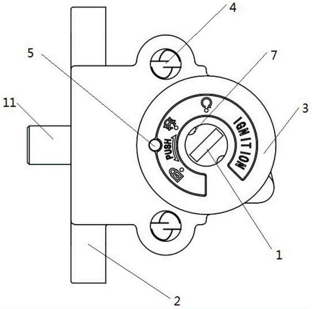
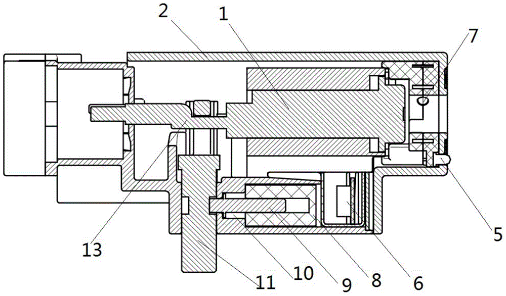
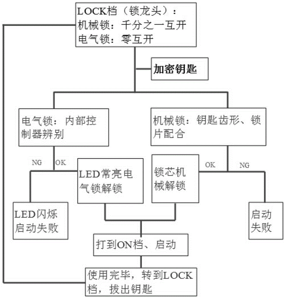
[0022] This embodiment provides an anti-theft lock with a key chip secondary locking mechanism, including an ignition lock cylinder 1, an ignition lock body 2, an ignition cover 3 for fixing the lock cylinder, and an anti-theft screw 4 with an S-shaped groove on the end surface. The ignition lock cylinder 1 is installed in the ignition lock body 2, and the ignition cover is fixed on the ignition lock body by the anti-theft screw 4. The ignition cover is also provided with an LED light 5, and is connected with the internal controller 6 installed in the ignition lock cylinder through the lug. Connected, the key insertion port of the ignition lock cylinder is provided with an input terminal 7, the input terminal 7 is connected to the internal controller 6 through a wire, and the internal controller controls the power on and off of the electromagnet 8 installed at the bottom of the ignition lock cylinder. Be provided with slide bar 9, slide bar end is provided with the back-moving ...


PUM


Abstract

The invention relates to a key chip secondary locking mechanism anti-theft lock, comprising an ignition lock cylinder, an ignition lock body as well as an ignition outer cover and anti-theft screws, which are used for fixing the lock cylinder, wherein the ignition lock cylinder is installed in the ignition lock body, the ignition outer cover is fixed on the ignition lock body through the anti-theft screws, a key inserting port of the ignition lock cylinder is provided with an input terminal, the input terminal is connected with an internal controller through a wire, the switching-on and switching-off of an electromagnet installed at the lower part of the ignition lock cylinder is controlled by the internal controller, a slide bar is arranged in the electromagnet, and a return spring for pushing the slide bar away from the electromagnet is arranged at the end of the slide bar; a crank is arranged at the tail end of the ignition lock cylinder, a locking shaft sleeves the crank, an annular groove is formed in the locking shaft, and when the ignition lock cylinder is in a closed state, the annular groove of the locking shaft is correspondingly matched with the slide bar arranged in the electromagnet. The adoption of the anti-theft lock provided by the invention is equivalent to the condition that a key lock is additionally arranged on a bolt of a directional lock, so that even if a lock cylinder anti-theft mechanism is broken and rotated, a locking mechanism of the bolt of the directional lock does not receive a digital signal of a key and is not unlocked, and then the directional lock can not be unlocked, thereby playing dual protection roles.

Description

technical field [0001] The invention belongs to the technical field of anti-theft locks, and relates to a locking mechanism, in particular to an anti-theft lock of a secondary locking mechanism of a key chip of a motorcycle or an electric vehicle and a locking method thereof. Background technique [0002] In order to prevent two-wheeled and three-wheeled motor vehicles such as motorcycles and battery cars from being stolen, people usually use locks to lock the handlebars or wheels of such vehicles. As for craftsmanship, most of the suspects in this area have been engaged in motor vehicle repairs, are professional in unlocking technology, can be familiar with the structure of vehicles, and are proficient in theft methods, mainly including keying locks, breaking car locks, disconnecting and connecting motorcycle lines, etc. The use of bolt cutters, screwdrivers, cross lock breaking tools, multi-model motorcycle keys, motorcycle ignition locks and other crime tools makes the an...

Claims


Application Information

Patent Timeline
Patent Type & Authority Applications(China)
IPC IPC(8): B62H5/00B60R25/22B60R25/24
Inventor 高双宝祝元健
Owner ZHENJIANG GANGLONG MECHANICAL & ELECTRICAL
Learn More