
Stereoscopic image display device

一种立体影像、显示装置的技术,应用在立体摄影术、立体系统、摄影等方向,能够解决易烦扰等问题

Inactive Publication Date: 2015-10-28
DAI NIPPON PRINTING CO LTD
View PDF7 Cites 6 Cited by
  • Summary
  • Abstract
  • Description
  • Claims
  • Application Information

AI Technical Summary

Problems solved by technology

The existing stereoscopic image display device assumes that the viewer wears glasses, which makes people easily disturbed and tired.

Method used


Image

  • Stereoscopic image display device
  • Stereoscopic image display device
  • Stereoscopic image display device

Examples


Embodiment Construction

[0036] Hereinafter, embodiments of the present invention will be described in detail with reference to the accompanying drawings. In addition, in the drawings of this specification, in order to facilitate illustration and understanding, scales and aspect ratios, etc. may be appropriately changed or exaggerated with respect to actual objects.

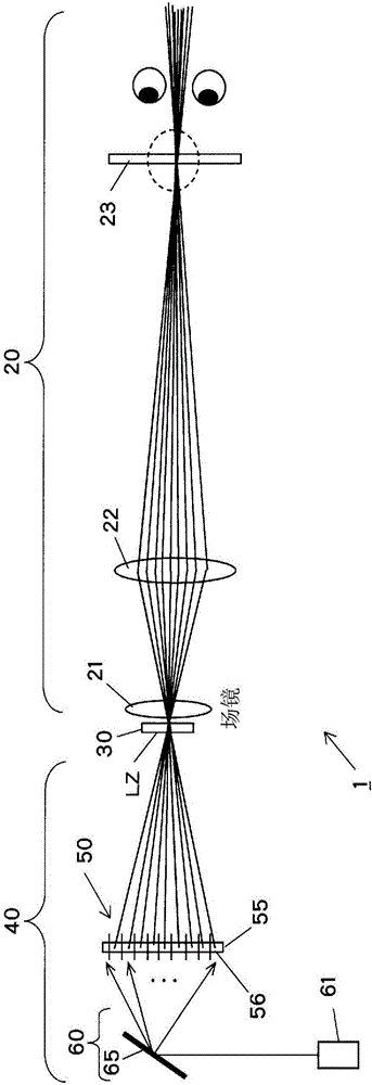
[0037] figure 1 It is a figure which shows the schematic structure of the stereoscopic image display apparatus which concerns on one Embodiment of this invention. figure 1 The stereoscopic image display device 1 includes an optical element 50 , an irradiation device 60 , a light modulator (SLM: Spatial Light Modulator: Spatial Light Modulator) 30 , and a projection optical system 20 .

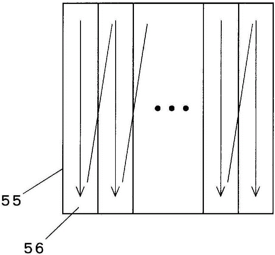
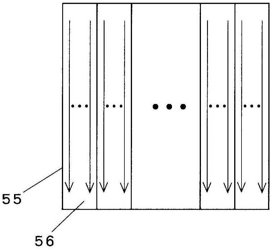
[0038] The optical element 50 has n regions 56 , and the n regions 56 are respectively provided corresponding to n (n is an integer of 2 or more) parallax images, and each can diffuse coherent light. The optical element 50 has, for example, a hologram r...


PUM


Abstract

[Problem] To provide a stereoscopic image display device that makes images with disparity viewable over a wide range of a diffusion surface. [Solution] A stereoscopic image display device (1) is provided with: an optical element (50) having n regions provided so as to correspond to each of n (n being an integer of 2 or higher) images with disparity for obtaining diffusing coherent light for each; an irradiating device (60) that irradiates the optical element with coherent light and scans the n regions with the coherent light; an optical modulator (30) that is illuminated by the diffused coherent light incident to each position on the optical element from the irradiation device, synchronizes for scanning the n regions with the coherent light, and generates modulated images corresponding to each of the n regions; and a projection optical system (20) that superimposes and projects each of the n images with disparity that have been generated by the modulated images onto the same surface at different angles.

Description

technical field [0001] The present invention relates to a stereoscopic video display device capable of displaying parallax images. Background technique [0002] A movie showing a stereoscopic image is an important topic, and a stereoscopic image display device is attracting attention. The conventional stereoscopic image display device presupposes that the observer wears glasses, and has a problem of being easily disturbed and fatigued. [0003] Therefore, a system in which a plurality of observers can see a stereoscopic image with naked eyes has been proposed and commercialized. For example, Japanese Patent Application Laid-Open No. 2007-240965 discloses a technique in which the direction of light is changed at high speed in a time-division system, and a multi-view directional image is displayed in a time-division system. In addition, a technique for displaying a stereoscopic image is disclosed in the Quarterly Report of the Information and Communication Research Institute...

Claims


Application Information

Patent Timeline
Patent Type & Authority Applications(China)
IPC IPC(8): G02B27/22G02B5/32G03B35/18G02B27/48G02B30/26H04N13/363
CPCG02B5/32G02B27/225G02B27/48G03B35/18H04N9/3129H04N13/0459G02B30/26H04N13/363H04N13/32H04N13/398G02B30/27
Inventor 仓重牧夫
Owner DAI NIPPON PRINTING CO LTD
Learn More