
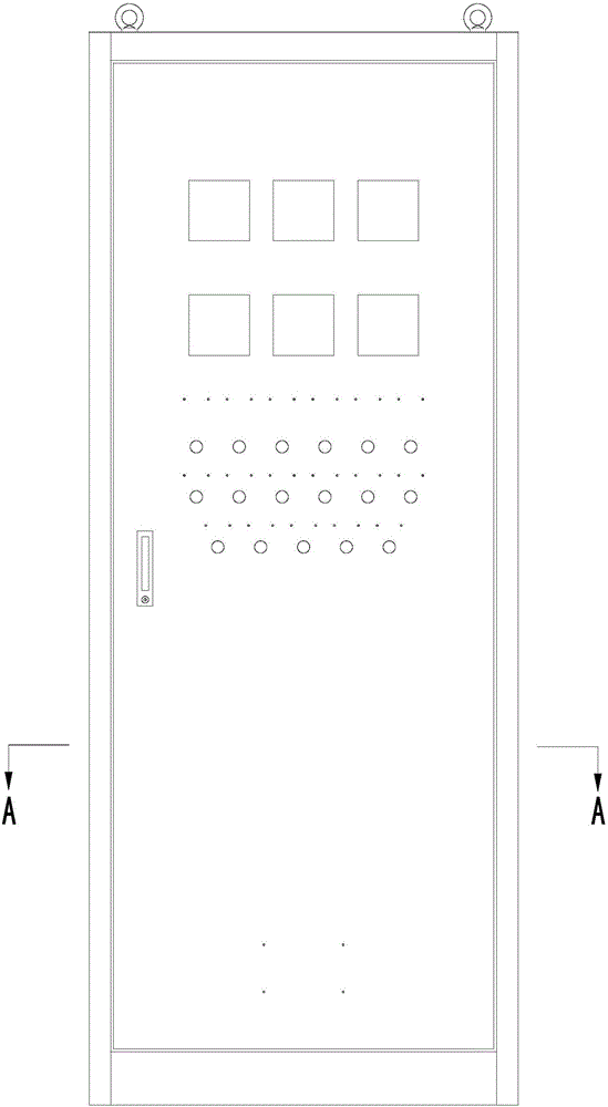
Electrical control cabinet with double panels for protection

A technology for electrical control cabinets and panels, applied in electrical equipment enclosures/cabinets/drawers, electrical components, chassis/boxes/drawer parts, etc., can solve misoperation, mechanical equipment failure, panel door splashing water And other issues

Inactive Publication Date: 2015-10-28
LUOYANG XINSILU ELECTRIC
View PDF6 Cites 7 Cited by
  • Summary
  • Abstract
  • Description
  • Claims
  • Application Information

AI Technical Summary

Problems solved by technology

Most of the operating keys, indicating instruments, buttons, knobs, operating rods and indicator lights of these operating elements are installed on the panel door of the control cabinet. The operating conditions of the various operating components are used to judge the operating status of the equipment. If the instrument and operating components fail or are damaged, it may cause the equipment on site to malfunction or be damaged. Moreover, these electrical components are charged bodies, which are very dangerous after damage. Safety, so it is very important to protect the various instruments and operating elements on the panel door
The current electrical control cabinet mainly has an outer panel. These instruments and operating components are installed on the outer panel and exposed outside. They are easily damaged and misoperated by others in the work site. At the same time, the environment in many work sites is not very good. Well, the dust is relatively large, and water may be splashed on the panel door during cleaning, which will easily damage the various instruments and electrical operating components of the panel door or cause various failures, and the sensitivity will decrease, which will further cause Failure or damage of mechanical equipment on site may cause casualties and is very dangerous

Method used


Image

  • Electrical control cabinet with double panels for protection
  • Electrical control cabinet with double panels for protection
  • Electrical control cabinet with double panels for protection

Examples


Embodiment Construction

[0036] In order to further explain the technical means and effects of the present invention to achieve the intended purpose of the invention, the specific implementation method, Structure, characteristic and effect thereof are as follows in detail.

[0037] see Figure 6 , Figure 7 , Figure 8 and Figure 11 , an electrical control cabinet protected by double-layer panels in the present invention is welded to each other by two front columns 1, two front cross braces 2, two rear columns 4, two rear cross braces 6, and four side braces 5. And constitute the frame of control cabinet, side plate 7, top plate 10 are fixedly connected with frame by screw respectively, and inner panel door 8, outer panel door 3 and rear door 9 are connected together with frame by hinge respectively.

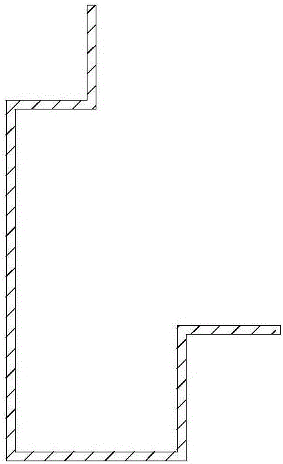
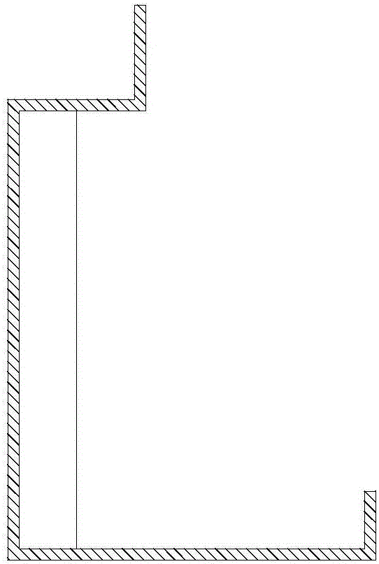
[0038] Specifically, see Figure 9 , the front column 1 of the control cabinet of the present invention is the front column of the existing cabinet frame (such as figure 2 (shown) extends inward...


PUM


Abstract

An electrical control cabinet with double panels for protection includes a front column, a front transverse support, a rear column, a rear transverse support, a side support, a side plate, a top plate, an outer panel door, an inner panel door, and a rear door. The front column, the front transverse support, the rear column, the rear transverse support and the side support are fixedly connected to each other to form a framework of the control cabinet. The side plate and the top plate are fixedly connected to the framework. The front column is provided with more than two steps. The front transverse support is also provided with more than two steps. The steps of the front column and the steps of the front transverse support form an inner door frame and an outer door frame respectively. The inner panel door is disposed on the inner door frame, and the outer panel door is disposed on the outer door frame. Through the above technical scheme, on the basis of a main body structure of a conventional electrical control cabinet, the electrical control cabinet of the invention is designed to have a structure with double panel doors, therefore, instruments and electrical operating elements on the inner panel door are protected from being damaged, and the outer panel door allows people to well observe running conditions of the instruments and electrical operating elements inside.

Description

technical field [0001] The invention belongs to the field of electrical control, and mainly relates to an electrical control cabinet protected by double-layer panels. Background technique [0002] The electrical control cabinet is mainly used to control the electrical operation of the mechanical equipment on site, and at the same time adjust different operations according to different actions on site. Most of the operating keys, indicating instruments, buttons, knobs, operating rods and indicator lights of these operating elements are installed on the panel door of the control cabinet. The operating conditions of the various operating components are used to judge the operating status of the equipment. If the instrument and operating components fail or are damaged, it may cause the equipment on site to malfunction or be damaged. Moreover, these electrical components are charged bodies, which are very dangerous after damage. Safety, so it is very important to protect the vari...

Claims


Application Information

Patent Timeline
Patent Type & Authority Applications(China)
IPC IPC(8): H05K5/00H05K5/02
Inventor 胡洛夷张永钢
Owner LUOYANG XINSILU ELECTRIC
Learn More