
Imaging spectrometer with grating as boundary

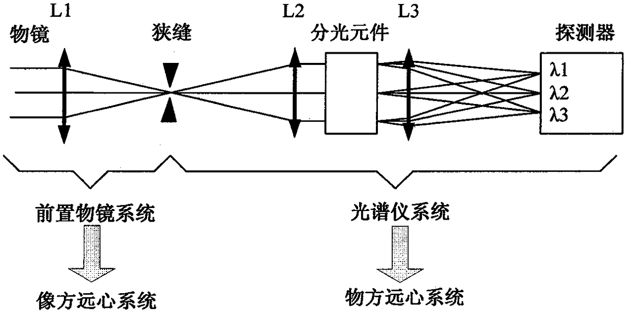
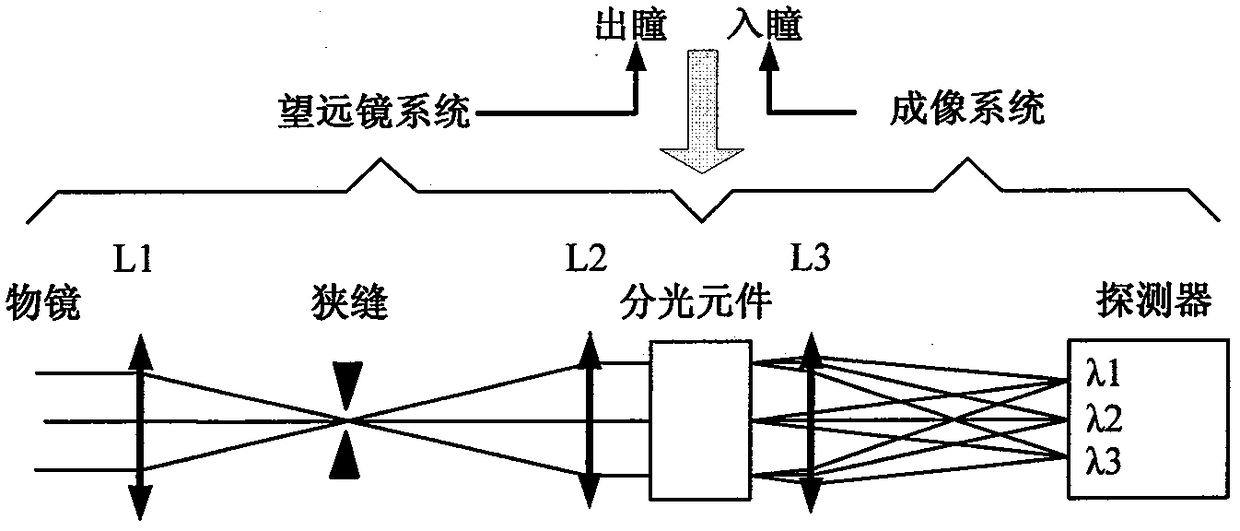
An imaging spectrometer and grating technology, which is applied in the field of imaging spectrometers, can solve the problems of inability to correct coma and astigmatism, high light energy utilization, low imaging resolution, etc., and achieves simple structure, low processing cost, spectral resolution and imaging resolution. high resolution effect

Active Publication Date: 2018-11-27
北京丰通丰创光电科技有限责任公司
View PDF4 Cites 0 Cited by
  • Summary
  • Abstract
  • Description
  • Claims
  • Application Information

AI Technical Summary

Problems solved by technology

The number of optical elements used is large, and high light energy utilization efficiency cannot be obtained. Due to its own limitations, the imaging resolution is also low, that is, it cannot correct coma and astigmatism at the same time.

Method used


Image

  • Imaging spectrometer with grating as boundary
  • Imaging spectrometer with grating as boundary
  • Imaging spectrometer with grating as boundary

Examples


Embodiment Construction

[0023] In the following, preferred embodiments according to the present invention will be described in detail with reference to the accompanying drawings.

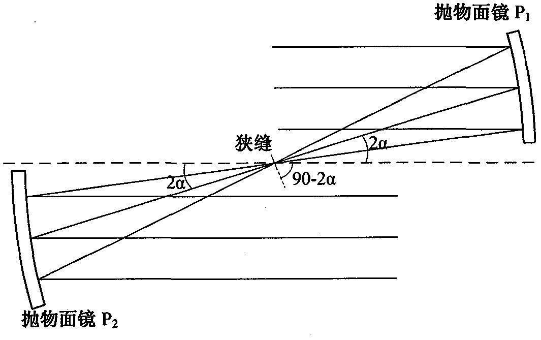
[0024] Image 6 Shown is an optical path diagram of an imaging spectrometer according to an embodiment of the present invention. The optical system of the imaging spectrometer includes: a primary mirror 1 in the telescope system (corresponding to the first mirror of the telescope system), a slit 2, a secondary mirror 3 in the telescope system (corresponding to the second mirror of the telescope system), a plane grating 4. The primary mirror 5 in the focusing optical system (corresponding to the primary mirror of the concentric off-axis double reflection system), the secondary mirror 6 in the focusing optical system (corresponding to the secondary mirror of the concentric off-axis double reflection system), and the array detector 7 .

[0025] The object to be observed is placed in front of the primary mirror 1 in the teles...


PUM


Abstract

An imaging spectrometer taking a grating as the boundary comprises a telescope system, a plane grating, a focusing system and an array detector, the telescope system is a double paraboloid reflector system, and the focusing system is a concentric off-axis bireflection system. The parallel light irradiates to the telescope system and then is irradiated out parallelly to be projected to the plane grating, a diffractive light beam on the plane grating is projected to a focusing optical system again and then is focused by the focusing optical system to be imaged on the array detector. By combining a front objective and a collimating optical system of a conventional plane grating imaging spectrometer together, the imaging spectrometer taking the grating as the boundary enables the lens number of the imaging spectrometer and the optical processing cost to be reduced and the luminous energy utilization rate to be improved.

Description

technical field [0001] The invention relates to the technical field of imaging spectroscopy, in particular to a grating dispersion imaging spectrometer, in particular to an imaging spectrometer with a grating as a boundary. Background technique [0002] Imaging spectroscopy technology originated from the multispectral remote sensing technology in the early 1980s. It is a new multi-dimensional information acquisition technology that combines imaging technology and spectral technology. It can obtain the spatial information and spectral information of the detected target. Due to its excellent information acquisition ability, it has been widely used in space exploration and surface observation, and has gradually become a powerful means of optical remote sensing detection. [0003] Grating dispersion imaging spectrometer Compared with other types of imaging spectrometers, grating dispersion imaging spectrometer has the advantages of high spectral resolution, wide band range, unif...

Claims


Application Information

Patent Timeline
Patent Type & Authority Patents(China)
IPC IPC(8): G01J3/28G01J3/02
Inventor 唐义李飞
Owner 北京丰通丰创光电科技有限责任公司
Learn More