Eureka AIR delivers breakthrough ideas for toughest innovation challenges, trusted by R&D personnel around the world.

Ultrasonic multi-point roadway surface displacement monitoring device

A surface displacement and monitoring device technology, applied to measuring devices, using ultrasonic/sonic/infrasonic waves, re-radiation of sound waves, etc., can solve the problems of large error in results, high cost of station installation, time-consuming and laborious, etc., and achieve sampling Increased frequency, reduced acquisition cost, wide range of applications

Inactive Publication Date: 2015-10-28
NORTH CHINA UNIVERSITY OF SCIENCE AND TECHNOLOGY
View PDF5 Cites 10 Cited by
  • Summary
  • Abstract
  • Description
  • Claims
  • Application Information

AI Technical Summary

Problems solved by technology

At present, the conventional test methods for this parameter are mainly the artificial cross-wire method and the convergent meter method, both of which are contact measurements, which are time-consuming and labor-intensive in application, and frequently interfere with traffic and ventilation, resulting in large error results and long acquisition cycles. The realization of real-time monitoring seriously restricts the improvement of safety management and construction technology
There are also very few cases of roadway surface displacement monitoring using photogrammetry, laser ranging and other technologies, but the installation cost of the measuring station is extremely high, and the data analysis is difficult, so it is not suitable for multi-point measurement of a large number of measuring stations

Method used


Image

  • Ultrasonic multi-point roadway surface displacement monitoring device
  • Ultrasonic multi-point roadway surface displacement monitoring device

Examples


Embodiment Construction

[0022] The following are specific embodiments of the present invention and in conjunction with the accompanying drawings, the technical solutions of the present invention are further described, but the present invention is not limited to these embodiments.

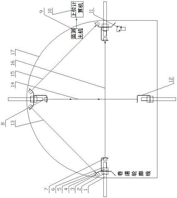
[0023] see figure 1 The ultrasonic multi-point roadway surface displacement monitoring device provided in this embodiment is composed of three parts: an ultrasonic transmitting / receiving transducer, a monitoring host 9, and a host computer 10. The ultrasonic transmitting / receiving transducer includes: installed in A separate receiving transducer R4 and a transmitting transducer T7 on the left side of the roadway, two separate transmitting transducers T7 and a transceiver integrated transducer RT8 installed at the top of the roadway, installed in the roadway The two split receiving transducers R4 on the right side form the upper triangle left side measurement line 13, the center line top and bottom measurement line 14, the ...


PUM


Abstract

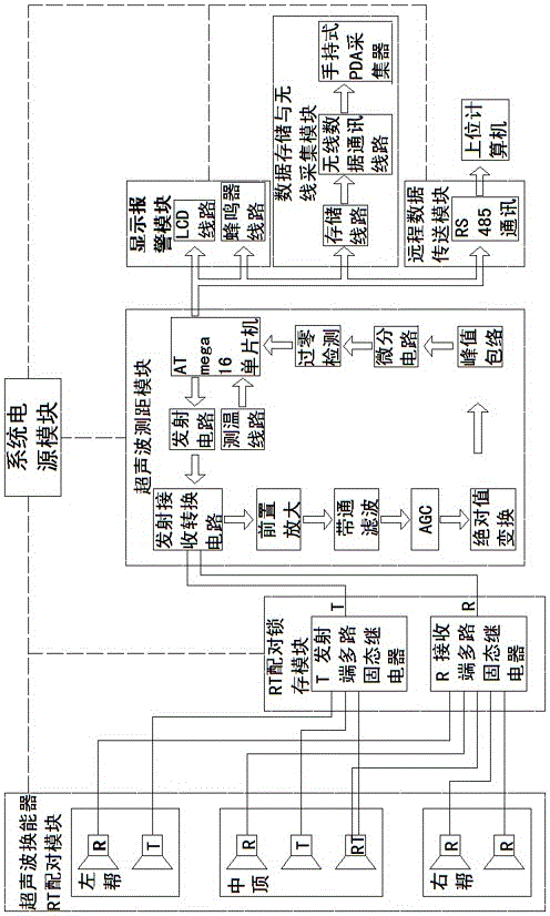
The invention relates to an ultrasonic multi-point roadway surface displacement monitoring device, which comprises a split type receiving transducer R and a transmitting transducer T which are arranged at the left side of a roadway, two split type transmitting transducers T and a receiving and transmitting integrated transducer RT which are arranged at the middle top of the roadway, and two split type receiving transducers R which are arranged at the right side of the roadway, thereby forming an upper triangular left side measuring line, a center line top bottom measuring line, an upper triangular right side measuring line and an upper triangular horizontal measuring line. Each split type receiving / transmitting transducer or integrated transducer adopts a four-core cable to be laid to a monitoring host along the roadway, and the monitoring host is connected with a remote upper computer through an RS485 or a wireless Zigbee. An RT matching latch module, an ultrasonic ranging module, a display alarm module, a data storage and wireless acquisition module, a remote data transmission module and a power supply module which are connected with the ultrasonic receiving / transmitting transducers are arranged inside the monitoring host. The ultrasonic multi-point roadway surface displacement monitoring device utilizes the ultrasonic ranging principle, and is stable in monitoring.

Description

technical field [0001] The invention relates to the field of support effect and safety anti-slump monitoring of rock mass engineering such as shafts, tunnels or chambers, and specifically relates to an ultrasonic multi-point roadway surface displacement monitoring device, which can be used in shafts, mine roadways, tunnels and other projects Surface displacement observation and monitoring of excavated space. Background technique [0002] In the construction of mine roadways, geotechnical tunnels and chambers, the four surface displacement observations of the surface of the excavation space, which are flat up, flat down, center left, and center right, are important indicators for evaluating the support effect and forewarning rock mass collapse. It is a mandatory inspection item limited by regulations and specifications. At present, the conventional test methods for this parameter are mainly the artificial cross-wire method and the convergent meter method, both of which are c...

Claims


Application Information

Patent Timeline
Patent Type & Authority Applications(China)
IPC IPC(8): G01B17/04G01S15/46
CPCG01B17/00
Inventor 刘建庄李佳刘红旗耿清友刘义生李建民李占金孙光华
Owner NORTH CHINA UNIVERSITY OF SCIENCE AND TECHNOLOGY
Why Eureka
Eureka Blog
Learn More