Variable-force viscous damper

A viscous damper, damping technology, applied in bridge parts, building components, bridges, etc., can solve the problems of reducing the protection effect of buildings, reducing, and failing to achieve, and achieve the effect of protecting the safety of the structure

Active Publication Date: 2015-10-28
NANJING DANFENG MACHINERY TECH
View PDF9 Cites 1 Cited by
  • Summary
  • Abstract
  • Description
  • Claims
  • Application Information

AI Technical Summary

Problems solved by technology

When an external force such as an earthquake or wind impacts the building structure, the building will sway, causing the piston of the viscous damper to reciprocate. When it moves to the two ends of the viscous damper, the viscous damper will be affected The load is the smallest. When the load is the smallest, sometimes the minimum force that can make the piston move cannot be reached, the piston cannot move, and the damper cannot consume the energy transmitted to the building by the external load. In this case, the viscous damper Reduced removal of externally input energy, thereby reducing building protection
In addition, in every disaster, the vibration suffered by the building is both large and small. When the small vibration is not within the range specified by the design code, the viscous damper will not generate displacement and cannot eliminate the vibration transmitted from the outside to the building. energy, the viscous damper cannot play a role in protecting the building

Method used


Image

  • Variable-force viscous damper
  • Variable-force viscous damper
  • Variable-force viscous damper

Examples


Embodiment 1

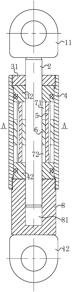
[0041] refer to figure 1 , a variable force viscous damper, including a master cylinder 4; the first sealing device and the second sealing device installed at the two ends of the master cylinder 4 respectively, the first sealing device and the second sealing device seal the inside of the master cylinder 4 The cavity forms a sealed cavity; a piston 6 that is arranged in the master cylinder 4 and can move axially, and the piston 6 divides the above-mentioned sealed cavity into a first sealed cavity 71 and a second sealed cavity 72; through the first sealing device, the piston 6 in turn And the piston rod 2 of the second sealing device, the piston rod 2 is fixedly connected with the piston 6; the damping medium filled in the first sealing cavity and the second sealing cavity.

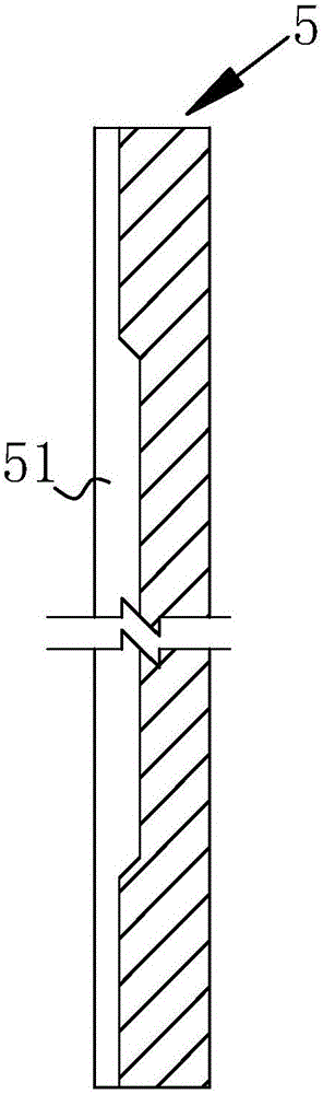
[0042] refer to figure 2 At least two damping through-holes 61 are uniformly arranged on the piston 2, and the central axis of the damping through-hole 61 is parallel to the central axis of the piston 2;...

Embodiment 2

[0055] In this embodiment, H12=0.5H11, H13=0.5H11;

[0056] S2=0.10S1;

[0057] L2=0.2L1, L3=0.2L1,

[0058] The meanings of all symbols in this embodiment are the same as in Embodiment 1.

[0059] The number of damping through holes is 5; the number of long slots on each damping major axis is 12.

Embodiment 3

[0061] In this embodiment, H12=0.3H11, H13=0.5H11;

[0062] S2=0.07S1;

[0063] L2=0.1L1, L3=0.2L1,

[0064] The meanings of all symbols in this embodiment are the same as in Embodiment 1.

[0065] The number of damping through holes is 8; the number of long slots on each damping major axis is 8.


PUM


Abstract

The invention discloses a variable-force viscous damper which comprises a main cylinder, sealing devices, a piston, a piston rod and damping media. The sealing devices are respectively mounted at two ends of the main cylinder, and an inner sealed cavity of the main cylinder is formed by the sealing devices; the piston capable of axially moving is arranged in the main cylinder; the piston rod penetrates the piston and the sealing devices and is fixedly connected with the piston; the sealed cavity is filled with the damping media; damping through holes are formed in the piston; damping long shafts are mounted in the damping through holes, and elongated slots are formed in the side walls of the damping long shafts; the elongated slots are divided into main elongated slots, first auxiliary elongated slots and second auxiliary elongated slots, and each first auxiliary elongated slot and the corresponding second auxiliary elongated slot are respectively formed in two ends of the corresponding damping long shaft; the depths of the two auxiliary elongated slots of each elongated slot are different from the depth of the main elongated slot of the elongated slot. The variable-force viscous damper has the advantages that external controllers and sensors can be omitted, generated force can be increased or reduced when the variable-force viscous damper moves to set positions according to requirements of working conditions, and building protecting effects still can be realized when vibration of the damper due to hazards such as earthquake or strong wind is over or under ranges specified by design specifications.

Description

technical field [0001] The invention belongs to the damper used in the technical field of shock resistance and vibration reduction, and in particular relates to a variable force viscous damper. Background technique [0002] Viscous dampers are now increasingly used in areas such as building structures and bridges, for vibration control of new buildings, and for seismic reinforcement of existing buildings. At present, viscous dampers have been used in many projects, mainly in high-rise buildings, towering structures, stadiums, bridges and railways. The control mechanism of the viscous damper is to consume part of the vibration energy of the structure through the damping material, so as to relieve the impact of the external load, reduce the vibration of the structure and protect the safety of the structure. [0003] At present, the damping force of the viscous damper used at home and abroad is subject to many technical indicators, including damping coefficient, index, speed a...

Claims


Application Information

Patent Timeline
Patent Type & Authority Applications(China)
IPC IPC(8): E04B1/98E01D19/00
Inventor 彭枫北房修春杨建国简万磊
Owner NANJING DANFENG MACHINERY TECH
Why Eureka
Try Eureka