
Directional and automatic-control bending machine and operation method thereof

An automatic control and bending machine technology, applied in the field of mechanical equipment, can solve problems such as low work efficiency, low pass rate, and easy mistakes, and achieve the effects of less labor force and intensity, high work efficiency, and zero scrap rate

Inactive Publication Date: 2015-10-28
中铁武汉电气化局集团第一工程有限公司
View PDF5 Cites 0 Cited by
  • Summary
  • Abstract
  • Description
  • Claims
  • Application Information

AI Technical Summary

Problems solved by technology

At present, the existing type bending machines in the market are manually braked, and it is easy to make mistakes in operation. The bending angle of the steel bar is not easy to grasp, and it is time-consuming and laborious, with low work efficiency and low pass rate.

Method used


Image

  • Directional and automatic-control bending machine and operation method thereof
  • Directional and automatic-control bending machine and operation method thereof
  • Directional and automatic-control bending machine and operation method thereof

Examples


Embodiment Construction

[0028] In order to better understand the purpose, features, and effects of the present invention, the technical solution of the present invention will be further described below in conjunction with specific examples.

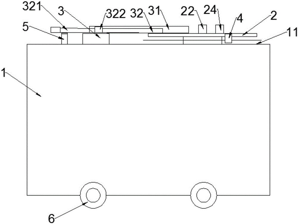
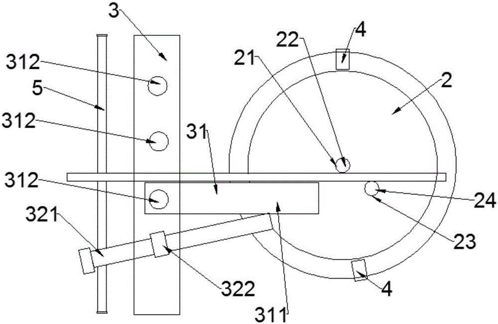
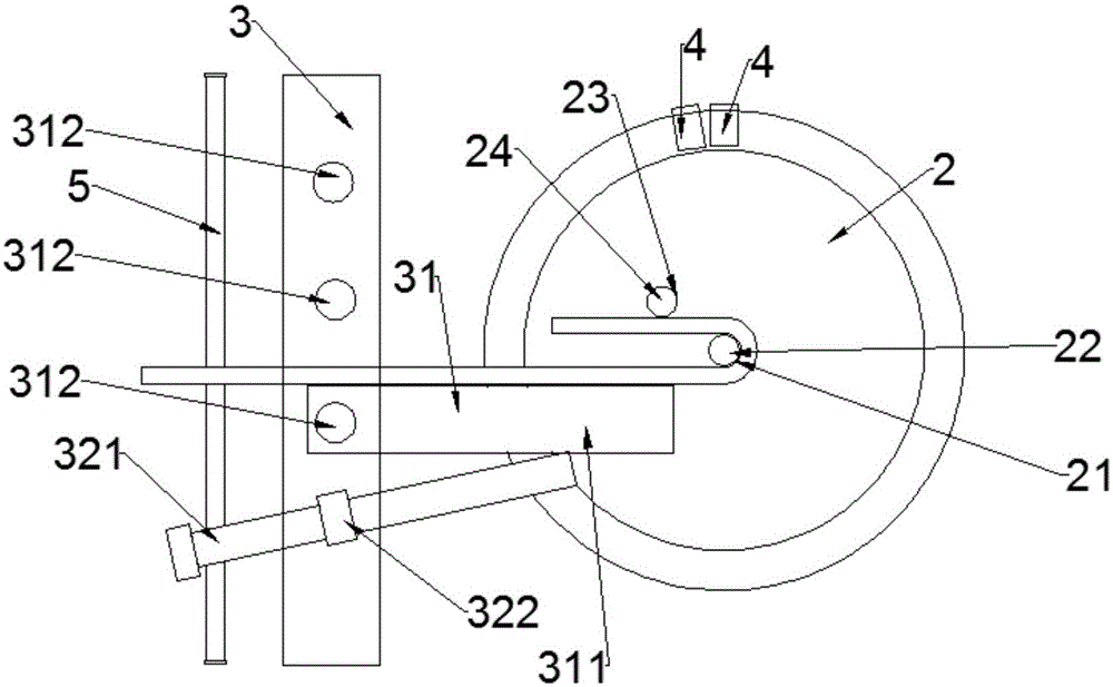
[0029] Such as Figure 1 to Figure 4 As shown, the directional automatic control bending machine includes: frame 1, table panel 11, work plate 2, center sleeve 21, center sleeve shaft 22, forming sleeve 23, sleeve bearing 24, insertion seat 3, support 5, stop Rib frame 31, support frame 32 and limit switch 4.

[0030] Such as Figure 1 to Figure 4 As shown, the frame 1 is provided with traveling wheels 6, and the traveling wheels 6 enable the frame 1 to move anywhere, which is convenient and fast; It is rotatably arranged on the table top 11, and a circular center sleeve 21 is arranged in the center of the working disk 2, and the center sleeve shaft 22 is arranged in the center sleeve 21, and the center sleeve shaft 22 is as high as On the working disk 2, the...


PUM


Abstract

The invention discloses a directional and automatic-control bending machine. The machine comprises a rack, a working plate, an insertion base, a transmission mechanism and a limiting switch, wherein a table plate is arranged on the rack; the working plate is rotationally arranged on the table plate, a round central sleeve is arranged in the middle of the working plate, a central sleeve shaft is arranged in the central sleeve, and a round forming sleeve and a sleeve bearing matched with the forming sleeve are further arranged on the working plate; the insertion base is fixedly arranged on the table plate, and a bar blocking frame is arranged on the insertion base; the transmission mechanism drives the working plate to rotate around the central sleeve shaft; the limiting switch is arranged on the table plate and can be used for setting the rotation angle of the working plate. The steel bars machined by the directional and automatic-control bending machine have the same bending degree and are attractive in appearance, the rejection ratio is zero, the work efficiency is high, little labor force is required, the labor intensity is low, and besides, a method is scientific, efficient, safe and simple.

Description

technical field [0001] The invention relates to a mechanical device, in particular to a directional automatic control bending machine for steel bars and an operation method thereof. Background technique [0002] In many projects, the bending of steel bars is the basic work content. When processing steel bars of φ6-φ40mm, one end of the steel bars needs to be bent into different semicircular models. At present, the existing type bending machines on the market are manually braked, which is easy to make mistakes in operation, and the bending angle of the steel bar is not easy to grasp, and it is time-consuming and labor-intensive, with low work efficiency and low pass rate. [0003] Therefore, it is necessary to design a directional automatic control bending machine for steel bars to overcome the above problems. Contents of the invention [0004] For the problems faced by the background technology, the object of the present invention is to provide a method that makes the ben...

Claims


Application Information

Patent Timeline
Patent Type & Authority Applications(China)
IPC IPC(8): B21F1/00
CPCB21F1/00
Inventor 杨明李伟华李顺成杨郝城王定正张良田
Owner 中铁武汉电气化局集团第一工程有限公司
Learn More