Discharge ionization current detector

一种放电离子化、电流检测器的技术,应用在仪器、测量装置、科学仪器等方向,能够解决难燃性气体灵敏度低、没有无机气体灵敏度等问题,达到良好测定结果、防止SN比的降低的效果

Active Publication Date: 2015-10-21
SHIMADZU SEISAKUSHO LTD
View PDF10 Cites 6 Cited by
  • Summary
  • Abstract
  • Description
  • Claims
  • Application Information

AI Technical Summary

Problems solved by technology

FID has low sensitivity to flammable gases and no sensitivity to inorganic gases

Method used


Image

  • Discharge ionization current detector
  • Discharge ionization current detector
  • Discharge ionization current detector

Examples


Embodiment Construction

[0057] Below, while referring to the attached Figure 1 Embodiments of the present invention will be described.

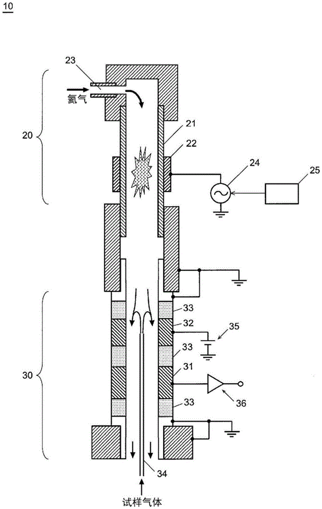
[0058] figure 1 It is a schematic configuration diagram of the discharge ionization current detector according to the first embodiment of the present invention, and shows a cross section of the discharge ionization current detector 10 which is made into a cylindrical shape. The discharge ionization current detector 10 is mainly composed of a plasma generation unit 20 and an ion collection unit 30 .

[0059] A gas introduction port 23 is provided above the plasma generating unit 20 , and a cylindrical tube 21 made of a dielectric such as synthetic quartz is provided below the plasma generating unit 20 . An electrode 22 for plasma generation is arranged outside the cylindrical tube 21 , and a low-frequency AC power supply 24 is connected to the electrode 22 . The voltage and frequency of the AC power supply 24 can be controlled by the controller 25 .

[0060] On ...


PUM

PropertyMeasurementUnit
purityaaaaaaaaaa
purityaaaaaaaaaa
purityaaaaaaaaaa

Abstract

This discharge ionization current detector is for use as a detector for gas chromatography and is suitable for analyzing components with high boiling points. A discharge ionization current detector (10) is configured primarily by a plasma generating unit (20) and an ion collecting unit (30). The ion collecting unit (30) has an ion collecting electrode (31) and a bias electrode (32) installed therein, and an insulating member made of 99.5% or higher purity aluminum oxide or sapphire is disposed between the ion collecting electrode (31) and the bias electrode (32).

Description

technical field [0001] The present invention mainly relates to a discharge ionization current detector suitable as a detector for a gas chromatograph (GC), and more specifically, relates to improvement of characteristics of the detector at high temperatures. Background technique [0002] As detectors for GC, hydrogen flame ionization detector (FID: Flame Ionization Detector), pulsed discharge ionization current detector (PDD: Pulsed Discharge Detector), thermal conductivity detector (TCD: Thermal Conductivity Detector) have been used. ) and other detectors in various ways. [0003] Among detectors, an FID is generally used to detect organic substances. The FID uses a hydrogen flame to ionize the sample components in the sample gas, and detects the ion current. The FID has an advantage of having a wide dynamic range, but since it uses a hydrogen flame to burn and ionize sample components, the compounds to be analyzed are limited. The FID has low sensitivity to flame retard...

Claims


Application Information

Patent Timeline
Patent Type & Authority Applications(China)
IPC IPC(8): G01N27/70G01N27/68G01N30/64
CPCG01N27/70G01N30/64G01N2030/647G01N2030/025
Inventor 堀池重吉品田惠
Owner SHIMADZU SEISAKUSHO LTD
Why Eureka
Try Eureka