Eureka AIR delivers breakthrough ideas for toughest innovation challenges, trusted by R&D personnel around the world.

Method and apparatus for measuring anesthetic depth

A technology of anesthesia depth and equipment, which is applied in the field of measuring anesthesia depth, can solve problems such as slow tracking speed, difficulty, and inaccurate monitoring of anesthesia depth, and achieve high compatibility, high utilization rate, and guaranteed utilization rate Effect

Active Publication Date: 2015-10-21
BRAINU CO LTD
View PDF4 Cites 5 Cited by
  • Summary
  • Abstract
  • Description
  • Claims
  • Application Information

AI Technical Summary

Problems solved by technology

[0005] With a conventional anesthesia depth monitoring device including, for example, a BIS analysis device, a user who is an anesthesia depth clinical subject or an anesthesia depth monitor cannot improve or change the brain wave analysis algorithm of the instrument so that an algorithm suitable for the patient's characteristics of the patient is possible Not used, and therefore cannot accurately monitor the patient's depth of anesthesia
In addition, since the details of the analysis algorithm installed in the instrument are not revealed, the device is not suitable for clinical anesthesia depth studies and there are many difficulties in proving the error of the algorithm
[0006] In addition, an anesthesia depth monitoring device such as a BIS analysis device has a problem that the patient's anesthesia state cannot be quickly sensed because the tracking speed for rapid changes in the anesthesia state is slow
[0007] Patent Document 1 is about a system and method for measuring brain activity and depth of anesthesia by electroencephalogram signal analysis, in which values ​​can be calculated very accurately compared with conventional spectral analysis, wavelet (wavelet) analysis, or entropy analysis, But the structure of the basic algorithm is very simple

Method used


Image

  • Method and apparatus for measuring anesthetic depth
  • Method and apparatus for measuring anesthetic depth
  • Method and apparatus for measuring anesthetic depth

Examples


Embodiment Construction

[0040] Hereinafter, specific embodiments for carrying out the present invention will be described with reference to the accompanying drawings. In the drawings, the size of main parts is exaggerated and auxiliary parts are omitted for clarity of illustration. Accordingly, the present invention should not be construed as limited to the accompanying drawings.

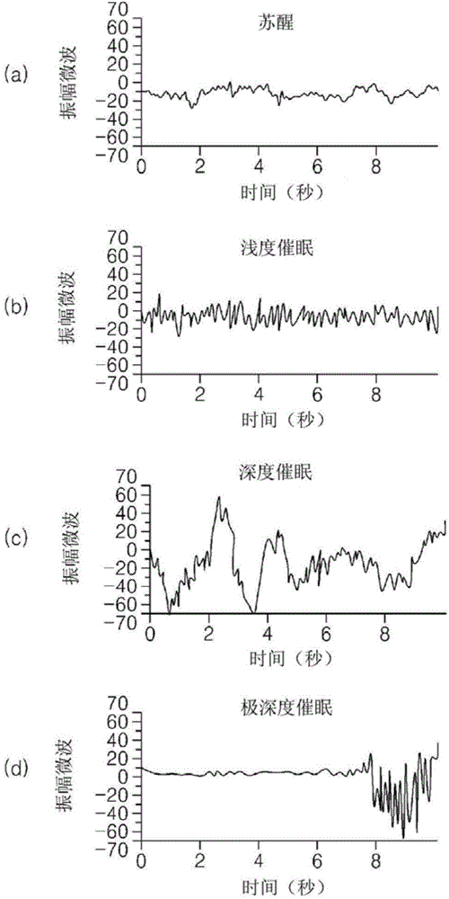
[0041] According to research, it is known that changes in characteristics of brain waves during surgery have a large correlation with the degree of anesthesia. see figure 1 , figure 1 (a) shows the measured brain waves during the wake-up state, and the brain waves during the wake-up state have small amplitude and high-frequency components. As the subject enters anesthesia (hypnosis), the amplitude becomes larger and the frequency components become lower, as in figure 1 (b) and figure 1 shown in (c). When the subject is very deeply anesthetized, the output is figure 1 Flat signal shown in (d), and a signal with high ...


PUM


Abstract

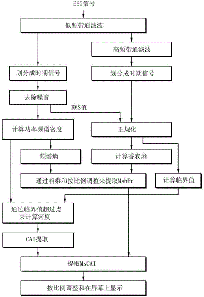
The present invention rapidly reacts to changes in the degree of anesthesia to provide an accurate and timely anesthetic depth measurement result, and a method for measuring anesthetic depth comprises the steps of: an epoch dividing portion generating an epoch signal by dividing a EEG signal into a plurality of numbers based on time units, a coefficient portion extracting a CAI calculation value (CAI) by calculating the number of points in an epoch having a value higher than an established critical value, a Shannon entropy calculating portion extracting a Shannon entropy calculation value (ShEn) by conducting a Shannon entropy-calculation from the EEG signal, and a spectra entropy calculating portion extracting a spectra entropy value (SpEn) by conducting a spectra entropy calculation; an improved Shannon entropy extracting portion extracting an improved Shannon entropy calculation value (MshEn) by multiplying the Shannon entropy calculation value (ShEn) and the spectra entropy calculation value (SpEn); and a CAI extracting portion extracting an anesthetic depth index (MsCAI) through logical operating of the improved Shannon entropy calculation value(MshEn) and the CAI calculation value (CAI).

Description

technical field [0001] The present invention relates to a method for measuring the depth of anesthesia, and more particularly, to a method and apparatus for measuring the depth of anesthesia, which can provide accurate measurements of the depth of anesthesia regardless of changes in anesthesia conditions, by Significantly improved tracking speed to timely provide anesthesia depth information according to changes in anesthesia conditions, and has compatibility with conventional anesthesia depth analysis equipment, thereby having high utilization. Background technique [0002] Typically, in the field of medical practice including surgery and therapy, when pain is applied to a subject, nerve transmission is prevented by anesthesia, so that the pain is removed or reduced. During surgery for a serious disease or condition, general anesthesia is administered and the patient under general anesthesia should be continuously observed. The patient's anesthesia status should be checked...

Claims


Application Information

Patent Timeline
Patent Type & Authority Applications(China)
IPC IPC(8): A61B5/04A61B5/048A61B5/0484A61B5/374
CPCA61B5/0476A61B5/048A61B5/4821A61B5/743A61B5/725A61B5/7257A61B5/374A61B5/369
Inventor 张祜宗金应徽朴祥贤洪承均金光武
Owner BRAINU CO LTD
Why Eureka
Eureka Blog
Learn More