Measurement method of vehicle-ground communication transmission delay in rail transit system

A vehicle-to-ground communication and rail transit technology, applied in the field of rail transit, can solve problems such as inappropriateness, complex channel conditions, and differences in transmission delays

Active Publication Date: 2018-08-07
BEIJING JIAOTONG UNIV
View PDF6 Cites 0 Cited by
  • Summary
  • Abstract
  • Description
  • Claims
  • Application Information

AI Technical Summary

Problems solved by technology

However, in the CBTC vehicle-to-ground communication system, due to the rapid movement of the train, the channel conditions are very complicated, handovers occur frequently, and the transmission delay of the uplink and downlink will be very different.
Therefore, traditional communication delay testing tools are not suitable for use in CBTC systems

Method used


Image

  • Measurement method of vehicle-ground communication transmission delay in rail transit system
  • Measurement method of vehicle-ground communication transmission delay in rail transit system

Examples


Embodiment 1

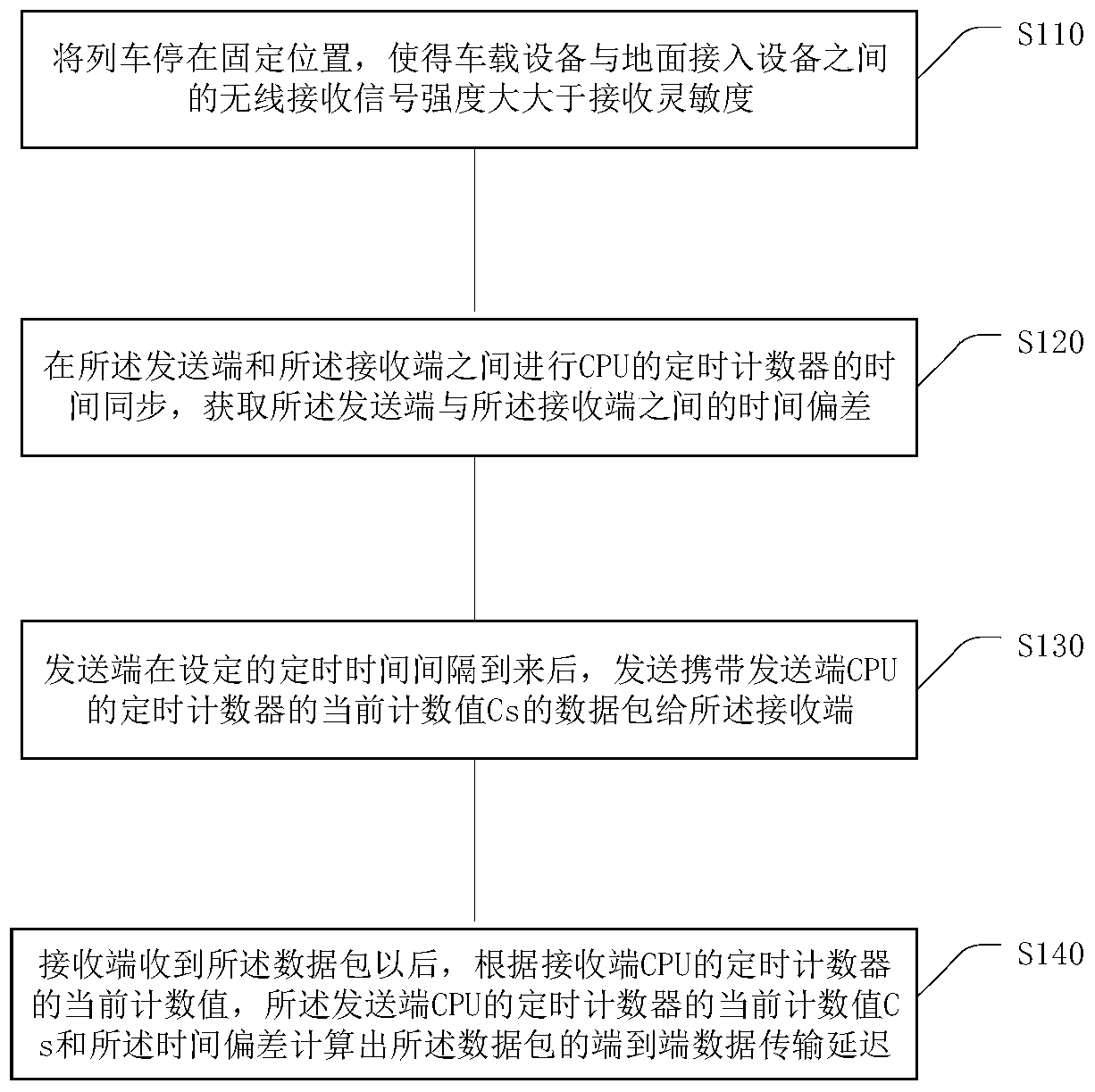
[0041] Aiming at the communication interruption time that may be caused by channel switching in the CBTC train-to-ground communication system, the present invention proposes a method for measuring the transmission delay of the train-to-ground communication in a rail transit system. The specific processing flow of the method is as follows figure 1 As shown, including the following processing steps:

[0042] Step S110: Stop the train at a fixed position so that the channel between the vehicle-mounted device and the ground access device is in a good line-of-sight environment, so that the strength of the wireless received signal between the vehicle-mounted device and the ground access device is greater than the receiving sensitivity. The aforementioned vehicle-mounted equipment may be a vehicle-mounted mobile station.

[0043] Step S120: The sender (which can be a vehicle-mounted device or a ground-access device) sends a data packet of a specified size at a specified time interval, and ...

Embodiment 2

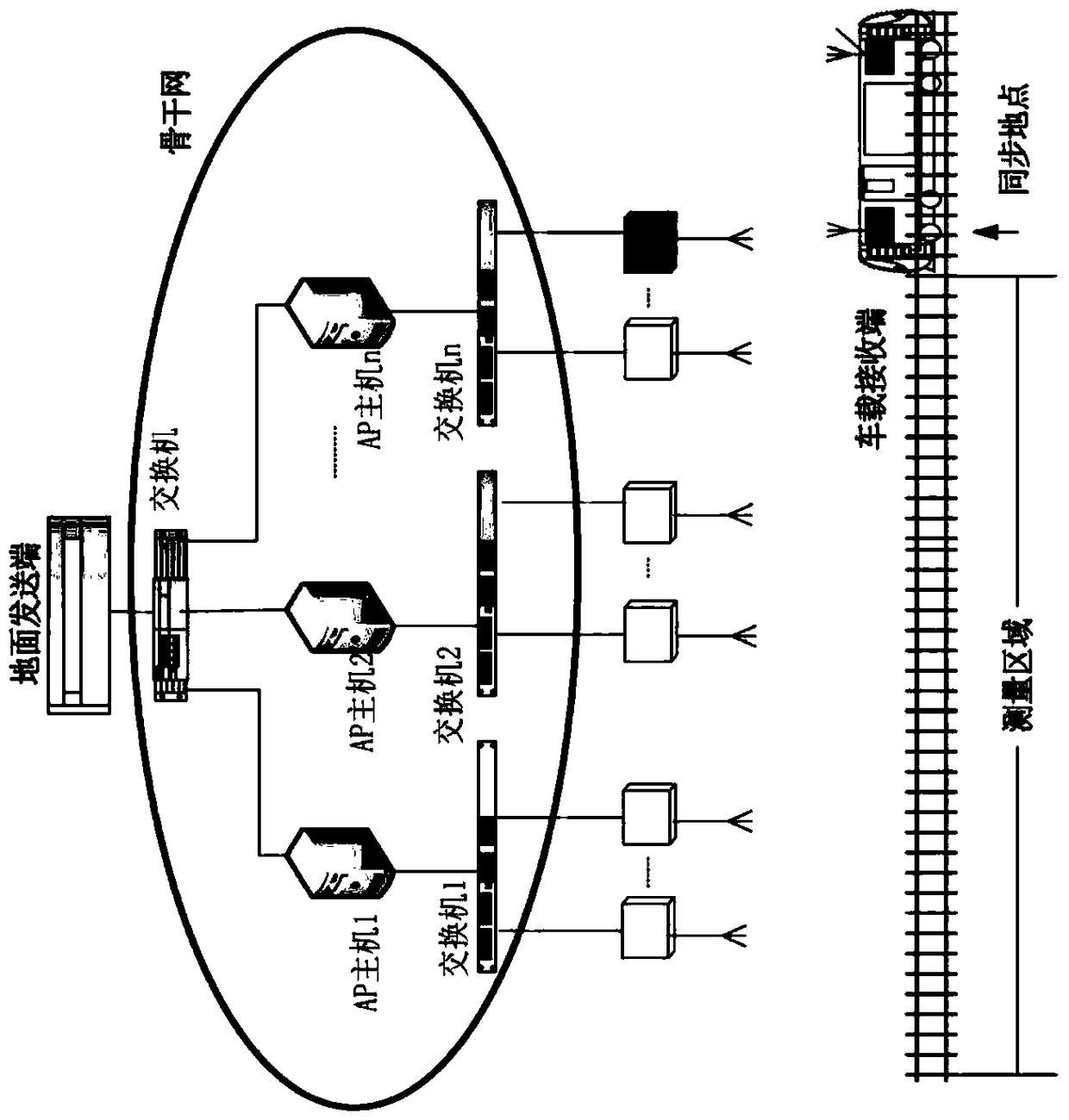
[0064] The structure of an urban rail transit vehicle-ground communication system provided by this embodiment is as follows figure 2 Shown. Let's take the measurement of the downlink transmission delay as an example (the uplink test is basically the same, only the position of the sender and receiver needs to be exchanged), such as figure 2 As shown, when the train is running out of the library, stop at a position with good channel conditions, and then complete the CPU running time synchronization between the sending end and the receiving end. The synchronization process is as follows:

[0065] UDP (User Datagram Protocol) communication is used between the sending device and the receiving device. The sending end adopts precise timing technology to read the timing frequency Fs of the precise timer of the sending device CPU and the value of the counter Cs, and use it twice The difference of the timer divided by the timing frequency of the timer is the timing interval. Once the ti...


PUM


Abstract

The embodiment of the invention provides a method for measuring train-ground communication transmission delay in a track traffic system. The method comprises the following steps: performing time synchronization of timing counters of CPUs (Central Processing Units) between a transmitting end and a receiving end, and acquiring a time deviation deltaa between the transmitting end and the receiving end; transmitting a data packet carrying the current count value Cs of the timing counter of the CPU of the transmitting end to the receiving end by the transmitting end after the arrival of a set timing time interval; and after the receiving end receives the data packet, calculating the end-to-end data transmission delay of the data packet according to the current count value Cr of the timing counter of the CPU of the receiving end, the current count value Cs of the timing counter of the CPU of the transmitting end and the time deviation deltaa. Through the embodiment of the invention, the uplink and downlink data transmission delay in the rapid moving process of a train in an urban track traffic system can be accurately measured.

Description

Technical field [0001] The present invention relates to the technical field of rail transit, in particular to a method for measuring the transmission delay of vehicle-to-ground communication in a rail transit system. Background technique [0002] With the rapid development of communication technology, especially radio technology, people began to study the CBTC system (Communication Based Train Control System) based on communication technology. The CBTC system uses wireless communication to transmit vehicle-ground two-way large-capacity information in a reliable and real-time manner. The train sends its own position, speed and other status information to the ground center in real time through the wireless communication network during operation. The ground center sends information such as obstacles ahead and temporary speed limits to the train through the wireless communication network. The train calculates the speed curve in real time based on the information of the obstacle ahea...

Claims


Application Information

Patent Timeline
Patent Type & Authority Patents(China)
IPC IPC(8): H04L12/26
CPCH04L43/0852
Inventor 朱力赵红礼蒋海林唐涛
Owner BEIJING JIAOTONG UNIV
Why Eureka
Try Eureka