
A fluidized bed waste incinerator

A technology of waste incinerator and fluidized bed, which is applied in the direction of fluidized bed combustion equipment, incinerator, and burning fuel in a molten state, and can solve problems such as shutdown of the furnace and poor slag discharge of the fluidized bed waste incinerator , to achieve the effects of reducing the concentration of formation, ensuring smooth slag discharge and clean combustion

Active Publication Date: 2018-05-22
JIMEI UNIV +1
View PDF6 Cites 0 Cited by
  • Summary
  • Abstract
  • Description
  • Claims
  • Application Information

AI Technical Summary

Problems solved by technology

[0008] The purpose of the present invention is to overcome the defects of the prior art and provide a fluidized bed garbage incinerator to solve the problems of poor slagging and frequent shutdown of the fluidized bed garbage incinerator

Method used


Image

  • A fluidized bed waste incinerator
  • A fluidized bed waste incinerator
  • A fluidized bed waste incinerator

Examples


Embodiment Construction

[0029] The present invention will be described in detail below in conjunction with the accompanying drawings.

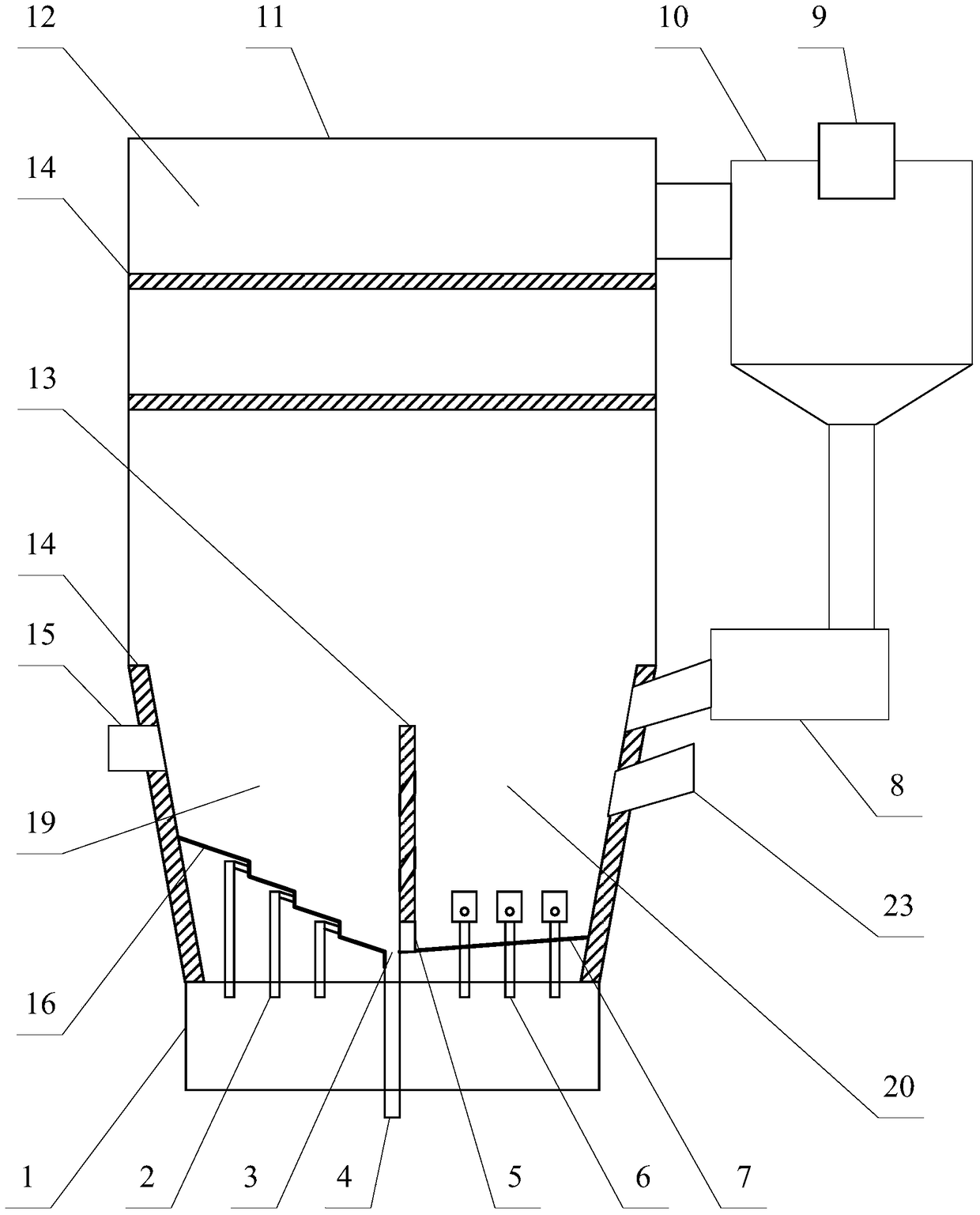
[0030] Such as figure 1 As shown, the present invention mainly includes a furnace 12, a partition wall 13, an inclined step-type air distribution plate 16, an air chamber 1, a directional air cap 2, an air cap 6, an air distribution plate 7, a feeder 8 and a separator 10.

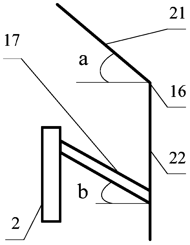
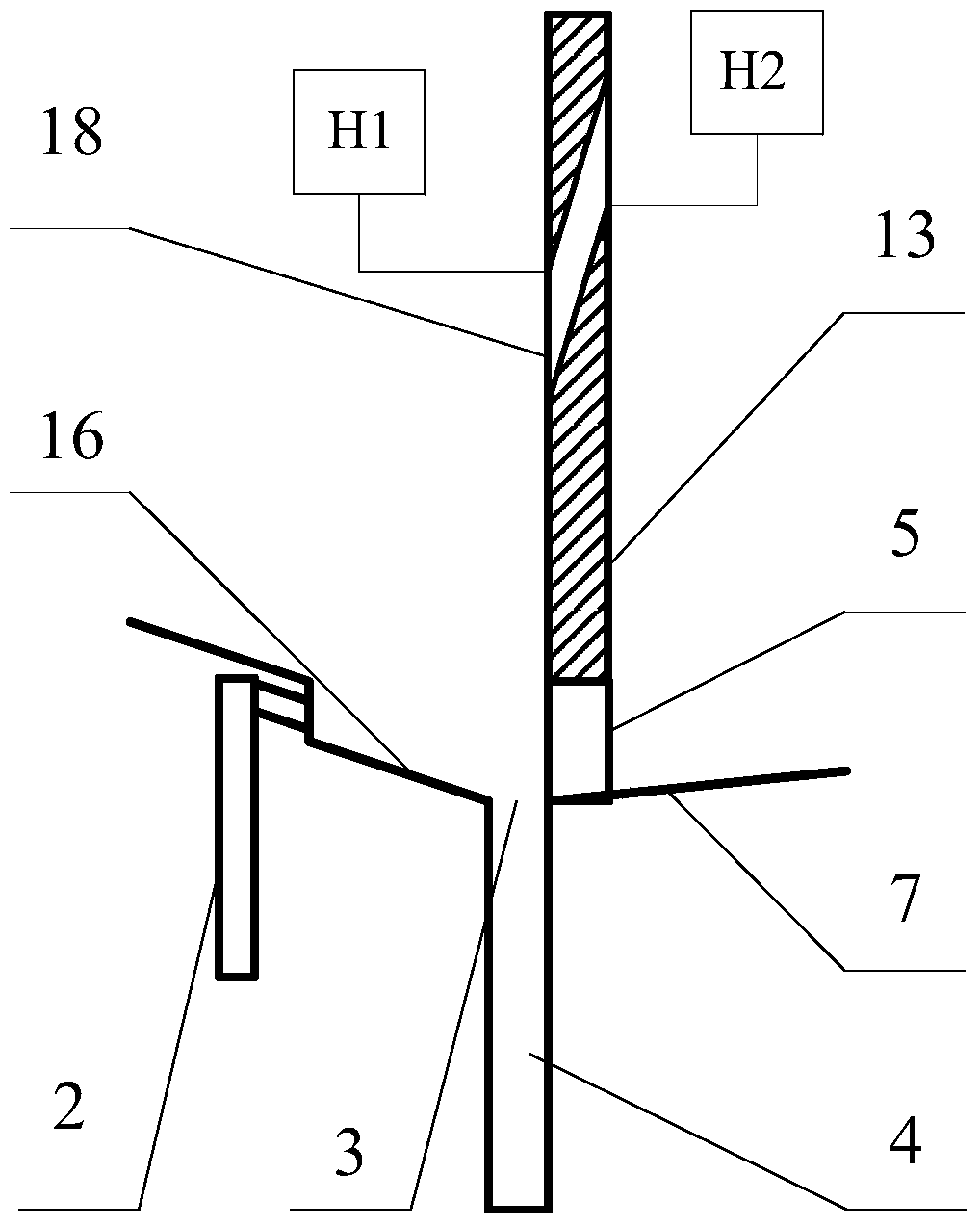
[0031] Furnace 12 is surrounded by water-cooled wall 11 to form a sealed structure. Partition wall 13 is set at the bottom of furnace 12. Both sides of partition wall 13 are divided into slag discharge area 19 and fluidization area 20. Garbage inlet 15 is set in slag discharge area 19 and slag discharge area 19 The lower part is equipped with an inclined step-type air distribution plate 16, and the lowest position of the inclined step-type air distribution plate 16 is provided with a slag discharge port 3, and the inclined step-type air distribution plate 16 is provided with a directional air cap ...


PUM


Abstract

The invention provides a fluidized bed garbage incinerator which comprises a hearth, and the hearth is surrounded by a water wall to be of a sealed structure. A partition wall is arranged on the lower portion of the hearth and divides the lower space of the hearth into a residue discharging zone and a fluidizing zone. A garbage inlet is formed in the residue discharging zone, and an inclined stepping type air distributor is obliquely arranged at the bottom of the residue discharging zone; a residue discharging opening is formed in the lowest position of the inclined stepping type air distributor, and directional caps are arranged on the inclined stepping type air distributor, wherein the air outlets of the directional caps are towards the residue discharging opening. Objects with large grain sizes and density in the residue discharging zone move towards the residue discharging opening along the inclined stepping type air distributor through the gravity effect and the blowing effect of the directional caps and then are discharged through a residue discharging pipe. The problems that a traditional fluidized bed garbage incinerator is difficult in residue discharging and high in failure rate and needs to discharge residues frequently after being stopped are effectively solved, the availability, safety, stability and economical efficiency of the fluidized bed garbage incinerator are improved, and operation and maintenance cost is greatly lowered.

Description

technical field [0001] The invention relates to the field of garbage incineration, in particular to a fluidized bed garbage incinerator. Background technique [0002] Garbage disposal is a problem that human beings all over the world must face together. If garbage cannot be effectively and safely disposed of, it will cause serious pollution to the living environment of human beings. In the past 20 years, the Chinese government has formulated a series of policies and regulations to vigorously promote the harmless disposal of waste. The number and capacity of waste treatment facilities in China have grown rapidly, and the overall urban environment has been greatly improved. By the end of 2010, the annual domestic garbage removal volume in cities and counties across the country was 221 million tons, and the harmless treatment rate of domestic garbage was 63.5%, of which 77.9% were in cities and 27.4% in counties ["Twelfth Five-Year Plan National Urban Life Construction Plannin...

Claims


Application Information

Patent Timeline
Patent Type & Authority Patents(China)
IPC IPC(8): F23G5/44F23C10/24
CPCF23G5/30F23G5/44F23G2203/50
Inventor 李志伟何秀锦
Owner JIMEI UNIV
Learn More