A tinplate clamping mechanism

A clamping mechanism, tinplate technology, applied in the directions of feeding device, positioning device, application, etc., can solve the problems of troublesome operation, tinplate falling off or offset, complex structure, etc., and achieve the effect of avoiding falling off and simple structure

Active Publication Date: 2016-09-28
广东金亨制罐有限公司
View PDF7 Cites 0 Cited by
  • Summary
  • Abstract
  • Description
  • Claims
  • Application Information

AI Technical Summary

Problems solved by technology

[0002] Metal cans are widely used in our production and life. The advantages of metal cans are very obvious. Its airtightness is very good, it can resist high internal pressure, and it can ensure that the products in the metal cans are not easy to expire. In the production of metal cans In the process, the can lid and the can body are produced separately, and finally assembled together to make it a complete metal can. During the production and processing of the metal can lid, the crankshaft press is generally used to drive the can lid mold on the tinplate. To press out the can lid, the existing tinplate needs to be fixed by a tinplate fixing device during the lid making process, so that the tinplate can be efficiently and accurately fed into the crank press for pressing. The existing tinplate fixing device has a complex structure and The operation is cumbersome, and it is difficult to firmly clamp and fix the tinplate during use, so that the tinplate often falls off or shifts during the process of processing the cover, which affects the processing efficiency and quality of the tinplate, and reduces the economic benefit, and the existing tinplate fixing device It is difficult to fix tinplate of various sizes and specifications, and the scope of application is narrow, and it is difficult to meet the needs of production and use

Method used


Image

  • A tinplate clamping mechanism
  • A tinplate clamping mechanism

Examples


Embodiment Construction

[0011] In order to further describe the present invention, a specific implementation of a tinplate clamping mechanism will be further described below in conjunction with the accompanying drawings. The following examples are explanations of the present invention and the present invention is not limited to the following examples.

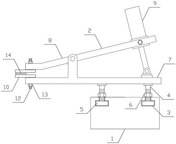
[0012] Such as figure 1 , figure 2 As shown, a tinplate clamping mechanism of the present invention includes a fixed plate 1 and a tinplate clamp 2, two tinplate clamps 2 are provided, and the two tinplate clamps 2 are horizontally and symmetrically arranged on both sides of the fixed plate 1, and the two sides of the fixed plate 1 are respectively A T-shaped guide groove 3 is arranged horizontally, locking screw rods 4 are arranged vertically on both sides below the tinplate fixture 2, and a translation block 5 is arranged at the lower end of the locking screw rod 4, and the translation block 5 is matched with the T-shaped guide groove 3 , the lock...


PUM


Abstract

The invention discloses a tinplate clamping mechanism, and belongs to the technical field of metal can manufacturing. The tinplate clamping mechanism comprises a fixed plate and tinplate fixtures. The two tinplate fixtures are horizontally and symmetrically arranged on the two sides of the fixed plate. T-shaped guide grooves are horizontally formed in the two sides of the fixed plate respectively. Locking lead screws are vertically arranged on the two sides of the lower portion of each tinplate fixture respectively. Horizontally-moving blocks are matched with the T-shaped guide grooves. Each tinplate fixture comprises a lower clamping plate, an upper clamping plate and a clamping cylinder. The middle of each upper clamping plate and the middle of the corresponding lower clamping plate are hinged to each other. The output ends of the clamping cylinders are connected with the lower clamping plates in a hinged mode. The clamping cylinders are connected with one ends of the upper clamping plates in a hinged mode. Tinplate clamping plates are horizontally arranged on the lower sides of the tinplate clamping ends of the upper clamping plates and the upper sides of the tinplate clamping ends of the lower clamping plates respectively. The tinplate clamping mechanism is simple in structure and can conveniently, efficiently and firmly clamp and fix tinplates of various sizes and specifications. The tinplate machining efficiency and quality are improved. Production and use requirements are met.

Description

technical field [0001] The invention belongs to the technical field of metal cans, and in particular relates to a tinplate clamping mechanism. Background technique [0002] Metal cans are widely used in our production and life. The advantages of metal cans are very obvious. Its airtightness is very good, it can resist high internal pressure, and it can ensure that the products in the metal cans are not easy to expire. In the production of metal cans In the process, the can lid and the can body are produced separately, and finally assembled together to make it a complete metal can. During the production and processing of the metal can lid, the crankshaft press is generally used to drive the can lid mold on the tinplate. To press out the can lid, the existing tinplate needs to be fixed by a tinplate fixing device during the lid making process, so that the tinplate can be efficiently and accurately fed into the crank press for pressing. The existing tinplate fixing device has a...

Claims


Application Information

Patent Timeline
Patent Type & Authority Patents(China)
IPC IPC(8): B21D43/00B21D51/38
CPCB21D43/00B21D51/38
Inventor 蒋炳荣
Owner 广东金亨制罐有限公司
Why Eureka
Try Eureka