
Lock-up clutch

A technology for locking clutches and moving plates, applied in the field of clutches, can solve the problems of poor heat dissipation performance of friction clutches, reduced reliability and service life of friction clutches, etc., and achieve the effects of good heat dissipation effect, good heat absorption capacity and simple working mode.

Pending Publication Date: 2015-10-07
CHONGQING YOUBO MACHINERY MFG
View PDF13 Cites 0 Cited by
  • Summary
  • Abstract
  • Description
  • Claims
  • Application Information

AI Technical Summary

Problems solved by technology

[0005] The invention provides a lock-up clutch to solve the problem that the existing friction clutch has poor heat dissipation performance, so that the reliability and service life of the friction clutch are reduced

Method used


Image

  • Lock-up clutch
  • Lock-up clutch

Examples


Embodiment Construction

[0021] The present invention will be further described below in conjunction with the accompanying drawings and examples, but not as a limitation to the present invention.

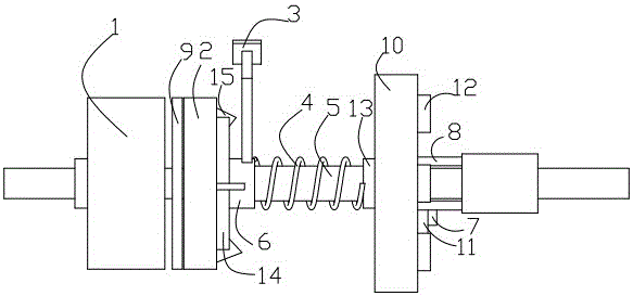
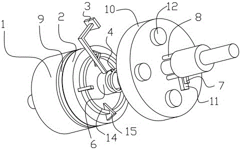
[0022] The reference signs in the figure are: flywheel 1, driven disc 2, pedal 3, compression spring 4, driven shaft 5, driven disc hub 6, microcontroller 7, electric push rod 8, friction plate 9, housing 10 , temperature sensor 11, electric fan 12, spring seat 13, support rib 14, blast rib 15.

[0023] Such as figure 1 As shown, a lock-up clutch includes a housing 10 and a flywheel 1 connected in the housing 10, a driven disc 2, a pedal 3, a compression spring 4, a driven shaft 5 and a driven disc hub 6, and the driven disc 2 Connected to the driven shaft 5 through the key of the driven disc hub 6, such as figure 2 As shown, the left side of the driven disc 2 is riveted with a friction plate 9, the friction plate 9 is frictionally connected to the flywheel 1, the right side of the driven disc 2 is sleev...


PUM


Abstract

The invention discloses a lock-up clutch and belongs to the field of clutches. According to the lock-up clutch, the side, back up to a flywheel, of a driven disk is provided with an annular supporting rib. The supporting rib is provided with a plurality of air blowing ribs. The air blowing ribs penetrate through the two sidewalls of the supporting rib and are arranged face to face. The surface of the driven disk and the surface of a shell are both provided with aluminum nitride layers. The shell is provided with an electric push rod, a microcontroller, a temperature sensor and an electric fan. The electric push rod penetrates through the shell and is connected with a spring base. A sleeve is arranged at the joint of the electric push rod and the outer surface of the shell. The microcontroller is electrically connected with the electric push rod, the temperature sensor and the electric fan. The lock-up clutch can provide effective cooling compensation for a hydraulic torque converter and has good heat absorption capacity and good ventilation and heat dissipation effects.

Description

technical field [0001] The invention relates to a clutch, in particular to a lock-up clutch. Background technique [0002] The clutch is located in the flywheel housing between the engine and the gearbox, and the clutch assembly is fixed on the rear plane of the flywheel with screws, and the output shaft of the clutch is the input shaft of the gearbox. During the driving process of the car, the driver can step on or release the clutch pedal as needed to temporarily separate and gradually engage the engine and the transmission, so as to cut off or transmit the power input from the engine to the transmission. Clutches are common components in mechanical transmissions that can disengage or engage the transmission system at any time. Commonly used clutches are divided into two types: jaw type and friction type. [0003] Friction clutch is the most widely used and oldest type of clutch. It is basically composed of friction plates, springs, driven discs and driven shafts. It is ...

Claims


Application Information

Patent Timeline
Patent Type & Authority Applications(China)
IPC IPC(8): F16H45/02
CPCF16H45/02F16H2045/0289
Inventor 陈明友
Owner CHONGQING YOUBO MACHINERY MFG
Learn More