A transmission method and device based on power line communication
A power line communication and transmission method technology, which is applied in the field of communication, can solve the problems of shortening the transmission distance of concentrators, reducing the efficiency of concentrator sending signals, and reducing the success rate of communication between concentrators and remote meters, so as to improve efficiency and ensure transmission Distance, the effect of improving the communication success rate
- Summary
- Abstract
- Description
- Claims
- Application Information
AI Technical Summary
Problems solved by technology
Method used
Image
Examples
Embodiment 1
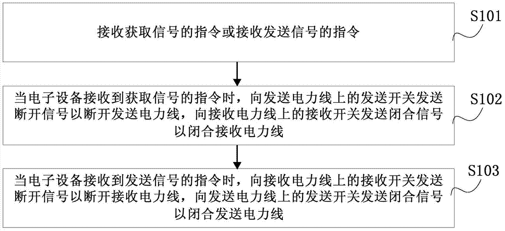
[0064] See figure 2 as shown, figure 2 The shown is a flowchart of a transmission method based on power line communication provided by the embodiment of the present invention. The method provided by this embodiment can be applied to an electronic device, and the electronic device can be a concentrator or other equipment. The method provided by the present invention The method can improve the success rate of communication between the electronic device and the terminal on the transmission power line, thereby improving the efficiency of the electronic device to send signals. The method includes:
[0065] Step S101, receiving an instruction for acquiring a signal or receiving an instruction for sending a signal;
[0066] Step S102, when the electronic device receives an instruction to acquire a signal, send an open signal to the sending switch on the sending power line to disconnect the sending power line, and send a closing signal to the receiving switch on the receiving powe...
Embodiment 2
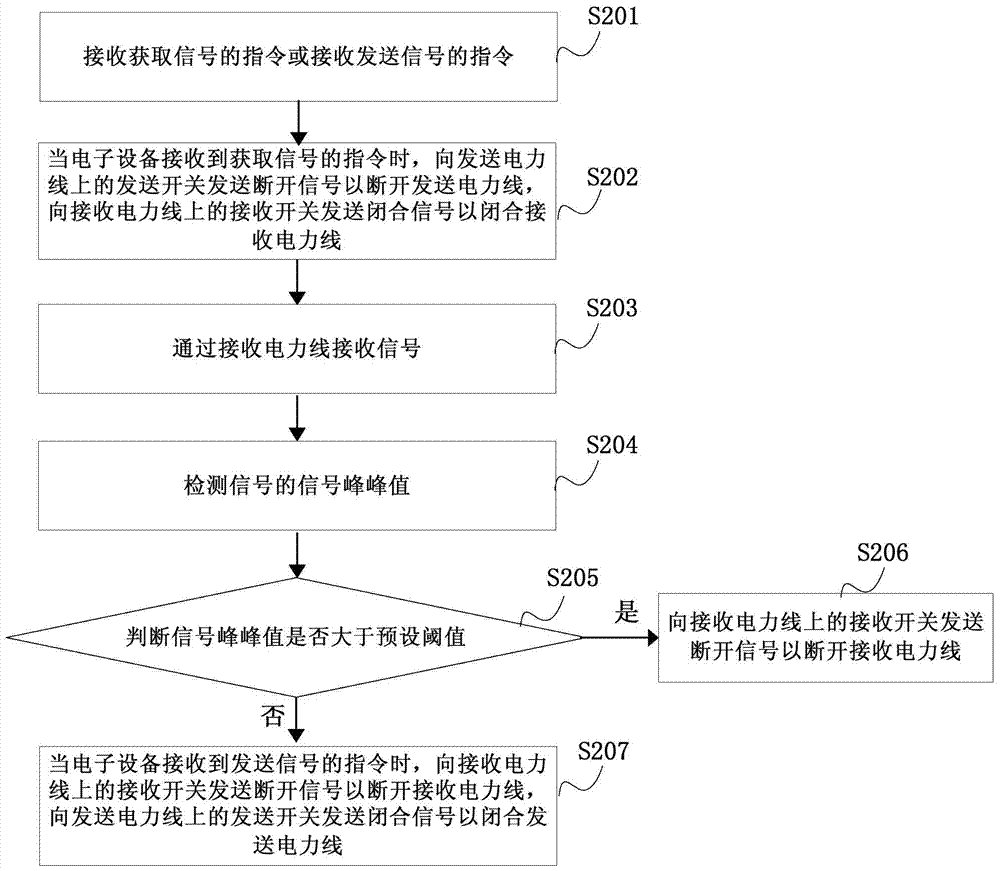
[0091] See image 3 as shown, image 3 The flow chart shown is another transmission method based on power line communication provided by the embodiment of the present invention. This embodiment is an extension on the basis of Embodiment 1. The method steps of this embodiment are repeated with Embodiment 1. For specific content, please refer to the content of Embodiment 1, which will not be repeated in this embodiment. The method provided by the invention can prevent excessive peak-to-peak voltage signals from entering the power line carrier chip, thereby preventing the occurrence of signal saturation, so as to ensure that the power line carrier chip will not be burned by excessive peak-to-peak voltage. The method includes:
[0092] Step S201, receiving an instruction for acquiring a signal or receiving an instruction for sending a signal;
[0093] Step S202, when the electronic device receives an instruction to acquire a signal, send an open signal to the sending switch on ...
Embodiment 3
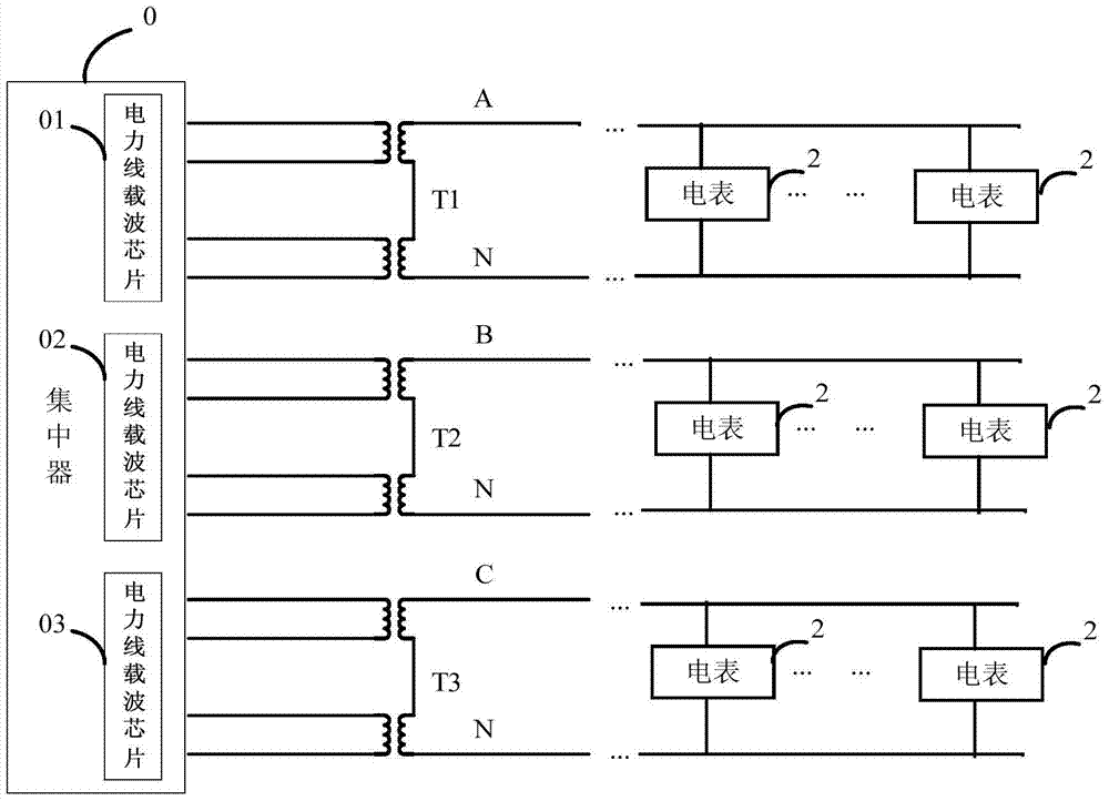
[0103] See Figure 4 as shown, Figure 4 Shown is a block diagram of a concentrator 1 provided by an embodiment of the present invention. The concentrator 1 is respectively connected to three transmission power lines and three reception power lines, and each transmission power line is provided with a transmission device that controls the opening or closing of the transmission power line. A switch, each receiving power line is provided with a receiving switch for controlling the opening or closing of the receiving power line.
[0104] exist Figure 4 In the shown embodiment, the concentrator 1 is mainly used to send an open signal to the transmitting switch on the transmitting power line to disconnect the transmitting power line when receiving an instruction to acquire a signal, and to send a closing signal to the receiving switch on the receiving power line To close the receiving power line; when receiving the instruction to send a signal, send an open signal to the receivin...
PUM
 Abstract
Description
Claims
Application Information
 - R&D Engineer
- R&D Manager
- IP Professional
- Industry Leading Data Capabilities
- Powerful AI technology
- Patent DNA Extraction
Browse by: Latest US Patents, China's latest patents, Technical Efficacy Thesaurus, Application Domain, Technology Topic, Popular Technical Reports.
© 2024 PatSnap. All rights reserved.Legal|Privacy policy|Modern Slavery Act Transparency Statement|Sitemap|About US| Contact US: help@patsnap.com


