
Ion implantation apparatus, final energy filter, and ion implantation method

A technology of ion implantation device and energy filter, which is applied in the direction of discharge tubes, electrical components, circuits, etc., and can solve the problems of non-interchangeability

Active Publication Date: 2015-09-30
SENCORP
View PDF8 Cites 8 Cited by
  • Summary
  • Abstract
  • Description
  • Claims
  • Application Information

AI Technical Summary

Problems solved by technology

Therefore, it is considered that different types of devices are not interchangeable in the use of ion implantation devices (such as semiconductor manufacturing processes)

Method used


Image

  • Ion implantation apparatus, final energy filter, and ion implantation method
  • Ion implantation apparatus, final energy filter, and ion implantation method
  • Ion implantation apparatus, final energy filter, and ion implantation method

Examples


Embodiment Construction

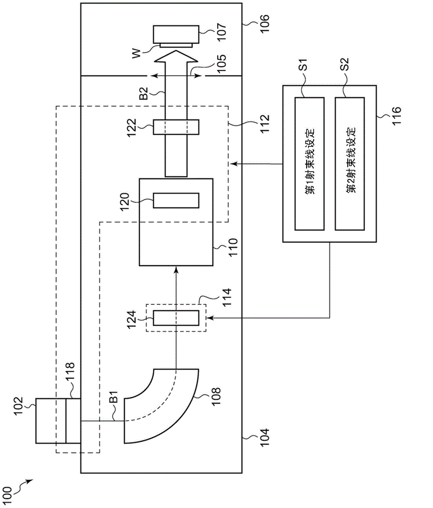
[0038] Hereinafter, modes for implementing the present invention will be described in detail with reference to the drawings. In addition, in description of drawings, the same code|symbol is attached|subjected to the same element, and repeated description is abbreviate|omitted suitably. In addition, the structures described below are examples and do not limit the scope of the present invention in any way. For example, in the following, a semiconductor wafer will be described as an example of an ion-implanted object, but other substances or members may also be used.

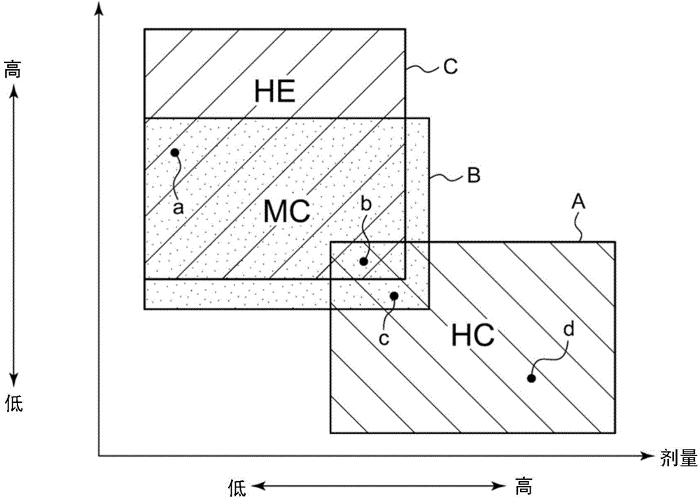
[0039] First, the procedure to achieve the embodiment of the present invention described later will be described. The ion implanter can select the type of ion to be implanted, and set its energy and dose according to the required characteristics to be built in the workpiece. Generally, ion implantation apparatuses are classified into several types according to the energy and dose range of implanted ions. Represe...


PUM


Abstract

A final energy filter includes a first adjustment electrode portion, an intermediate electrode portion, and a second adjustment electrode portion. The final energy filter further includes a power supply unit. The power supply unit is configured such that it applies the voltages separately to the first adjustment electrode portion, the intermediate electrode portion, and the second adjustment electrode portion. The power supply unit applies voltages to an upstream auxiliary electrode portion, a deflection electrode portion and a downstream auxiliary electrode portion, respectively, such that the energy range of ion beam in a first region between the upstream auxiliary electrode portion and the deflection electrode portion is approximately equal to that in a second region between the deflection electrode portion and the downstream auxiliary electrode portion.

Description

technical field [0001] This application claims priority based on Japanese Patent Application No. 2014-067156 filed on March 27, 2014. The entire content of the application is incorporated in this specification by reference. [0002] The present invention relates to an ion implantation, and more specifically, to an ion implantation device and an ion implantation method. Background technique [0003] An ion source and its power supply are connected to an ion implantation apparatus so that an ion beam with a small beam current is extracted from the ion source (for example, refer to Patent Document 1). In this device, the connection between the ion source and the power supply can be changed, so that the ion beam with a larger beam current is extracted from the ion source. [0004] Another ion implantation device has an ion source, an accelerating tube, and an electrical circuit connected to their power sources, so that ions can be implanted into a target with high ion energy (...

Claims


Application Information

Patent Timeline
Patent Type & Authority Applications(China)
IPC IPC(8): H01J37/317
CPCH01J37/3171H01J2237/057H01J37/3007H01J37/147H01J37/05H01J37/063
Inventor 八木田贵典
Owner SENCORP
Learn More