Eureka AIR delivers breakthrough ideas for toughest innovation challenges, trusted by R&D personnel around the world.

Constant-volume combustion technology adopting rotating valve to control opening and closing of combustion chamber and power system applying constant-volume combustion technology

A constant volume combustion and combustion chamber technology, applied in the combustion chamber, continuous combustion chamber, combustion method and other directions, can solve the problems of small intake area valve area, unfavorable flow rate, low utilization rate of windward area, etc., to improve the thrust-to-weight ratio, The effect of simple implementation and reduced processing difficulty

Active Publication Date: 2015-09-30
北京首赫防务科技有限公司
View PDF9 Cites 1 Cited by
  • Summary
  • Abstract
  • Description
  • Claims
  • Application Information

AI Technical Summary

Problems solved by technology

After research, this type of rotary valve firstly has reliability problems in the face seal; secondly, the utilization rate of this type of rotary valve for the windward area is low, that is, the air intake area is extremely small compared to the valve area, which is not conducive to improving the overall performance. flow

Method used


Image

  • Constant-volume combustion technology adopting rotating valve to control opening and closing of combustion chamber and power system applying constant-volume combustion technology
  • Constant-volume combustion technology adopting rotating valve to control opening and closing of combustion chamber and power system applying constant-volume combustion technology
  • Constant-volume combustion technology adopting rotating valve to control opening and closing of combustion chamber and power system applying constant-volume combustion technology

Examples


Embodiment Construction

[0031] In order to make the purpose of the present invention, the technical solution and a bit clearer, the technical solution of the present invention will be clearly and completely described below. All other implementations obtained below fall within the protection scope of the present invention.

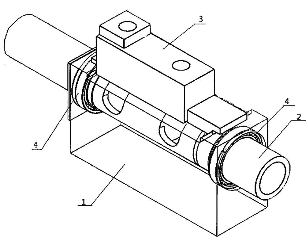
[0032] Such as figure 1 As shown, the device for implementing the constant volume combustion technology proposed by the present invention mainly includes a base 1 , a rotating shaft 2 , and a combustion chamber 3 .

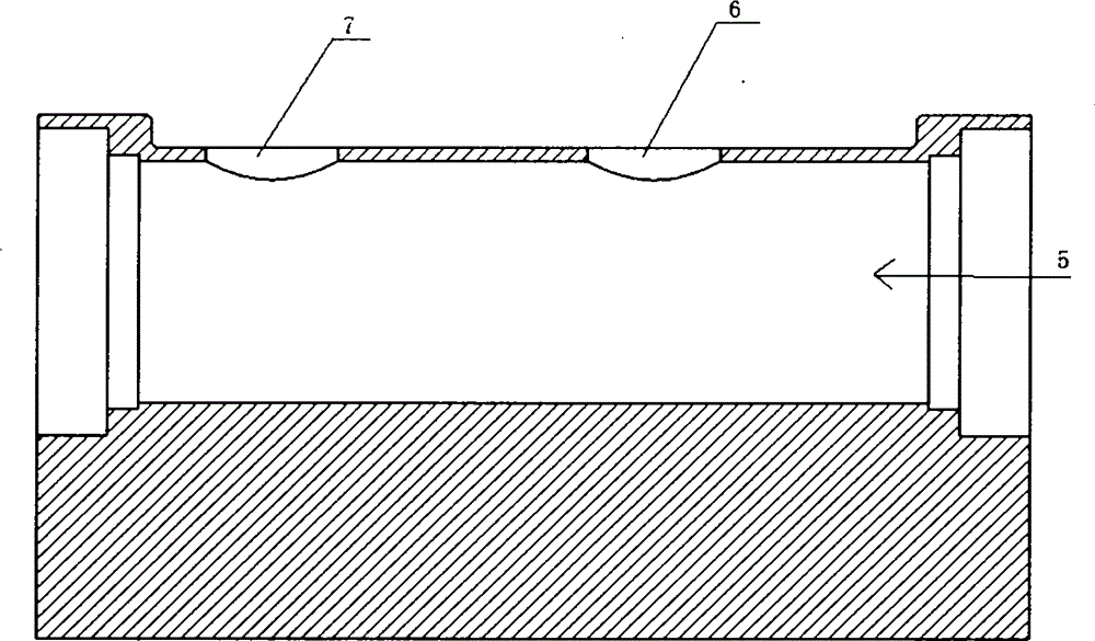
[0033] Such as figure 2 As shown, the middle of the base 1 is provided with a stepped through hole 5 , and the top of the base 1 is axially from the front to the back air intake hole 6 and exhaust hole 7 .

[0034] Such as image 3 As shown, the front end and the rear end of the rotating shaft 2 are respectively provided with an air intake passage 8 and an exhaust passage 9, and the two are not connected. The rotating shaft 2 is axially provided with an inlet pas...


PUM


Abstract

The invention relates to the technical field of combustion, in particular to a constant-volume combustion technology adopting a rotating valve to control opening and closing of a combustion chamber and a power system applying the constant-volume combustion technology. A device used for the constant-volume combustion technology comprises a base, a rotating shaft and the combustion chamber; a stepped through hole is formed in the base and matched with the rotating shaft in mounting; a gas inlet and a gas outlet are axially formed in the middle section of the top of the base and matched with a gas inlet and a gas outlet of the combustion chamber in mounting in a penetrated manner; a gas inlet passage and a gas outlet passage are axially formed in the rotating shaft; a gas inlet passage outlet groove is formed in the front section of the rotating shaft and communicated with the gas outlet passage and cooperates with the gas outlet in the top of the base to control opening and closing of the combustion chamber; a flow rectifying blade is arranged inside the combustion chamber. The constant-volume combustion technology has the advantages that the device can cooperate with the fixed base and the combustion chamber through the rotatable rotating shaft to control opening and closing of the combustion chamber so as to achieve constant-volume combustion, and the device is simple in structure and reliable in working.

Description

technical field [0001] The invention relates to the field of combustion technology, in particular to a constant-volume combustion technology using a rotary valve to control the opening and closing of a combustion chamber and a power system using the technology. Background technique [0002] The existing constant-volume combustion technologies are mainly divided into two categories: one is the constant-volume combustion form applied to piston internal combustion engines; the other is the constant-volume combustion form applied to jet propulsion devices. The invention is a novel constant-volume combustion technology proposed for a jet propulsion device. [0003] The constant volume combustion technology currently applied to jet propulsion devices is mainly pulse detonation (PDE) technology. In essence, PDE achieves the purpose of constant volume combustion by controlling the detonation wave that propagates rapidly downstream along the pipeline. A series of Complicated aerodyn...

Claims


Application Information

Patent Timeline
IPC IPC(8): F23R3/58
Inventor 龚雨晋王腾
Owner 北京首赫防务科技有限公司
Why Eureka
Eureka Blog
Learn More