
Motor Vehicle Muffler

A muffler and motor vehicle technology, which is applied in the direction of machines/engines, mufflers, mechanical equipment, etc., can solve the problems of short service life and high production cost of the muffler, and achieve the effect of improving muffler volume and good buffering effect

Active Publication Date: 2018-03-13
柳州利和排气控制系统有限公司
View PDF7 Cites 1 Cited by
  • Summary
  • Abstract
  • Description
  • Claims
  • Application Information

AI Technical Summary

Problems solved by technology

[0003] The technical problem to be solved by the present invention is to provide a motor vehicle muffler with good noise reduction effect to solve the problems of short service life and high production cost of existing mufflers

Method used


Image

  • Motor Vehicle Muffler
  • Motor Vehicle Muffler

Examples


Embodiment 1

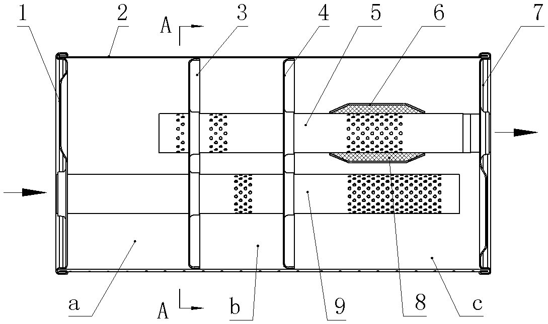
[0013] like figure 1 and figure 2 The motor vehicle muffler shown includes a casing provided with an air intake pipe 9 and an air outlet pipe 5. The casing is formed by connecting the front end cover 1, the rear end cover 7 and the cylinder body 2, and the cylinder body 2 is formed by two layers of overlapping steel plate locking seams. Enclosed, the thickness of the two layers of steel plates is the same and both are 0.6 mm. The connection between the cylinder body and the front end cover 1 and the rear end cover 7 is the end cover crimping connection, and the edge of the rear end cover 7 is provided with a drainage through hole; The inner space is divided into a first chamber a, a second chamber b and a third chamber c by the first baffle plate 3 and the second baffle plate 4 with holes along the intake direction. The edge of the partition plate 4 is provided with a drainage gap, and the first partition plate 3 and the second partition plate 4 are provided with a plurality...

Embodiment 2

[0015] The number of through holes on the perforated pipe section of the third chamber c of the intake pipe 9 is 5 times that of the number of through holes on the perforated pipe section of the second chamber b; The third chamber c is respectively provided with a perforated pipe section on which a plurality of through holes are distributed, and the sum of the equivalent areas of the holes on the two perforated pipe sections of the intake pipe 9 is the hole in the second chamber b of the exhaust pipe 5 2.1 times the sum of the flow area of ​​the through hole on the pipe section and the hole on the first partition; the first partition 3 and the second partition 4 are provided with a plurality of holes with a diameter of 4 mm and a diameter of 20 mm. The large holes 10, the plurality of 4 mm holes 11 on the first separator 3 and the second separator 4 are evenly distributed; other features are the same as those in Embodiment 1.

[0016] During operation, the airflow enters from ...


PUM


Abstract

The invention discloses a motor vehicle muffler, which relates to the technical field of automobile muffler manufacture, and comprises a casing provided with an air inlet pipe and an air outlet pipe, and the inner space of the casing is surrounded by a first partition plate and a second partition plate with holes. The air intake direction is divided into a first chamber, a second chamber and a third chamber. The end of the air intake pipe is blocked and extends into the third chamber through two partitions in sequence. The trachea is respectively provided with a perforated pipe section with a plurality of through holes distributed thereon in the second chamber and the third chamber; the air outlet pipe is in the first chamber, the second chamber and the The third chamber is respectively provided with a perforated pipe section on which a plurality of through holes are distributed, and the air outlet pipe is provided with a high-frequency casing outside the perforated pipe section in the third chamber, and the high-frequency A sound-absorbing material is provided between the casing and the wall of the outlet pipe. Compared with the prior art, the invention can solve the problems of short service life and high production cost of the existing muffler.

Description

technical field [0001] The invention relates to the technical field of automobile muffler manufacturing, in particular to a muffler used for a motor vehicle with a small-displacement engine. Background technique [0002] For motor vehicles with smaller displacement engines, two-stage mufflers are usually configured due to the limitation of the installation position of the vehicle chassis. There is a one-stage muffler. The muffler includes a casing with inlet and outlet pipes. The inner space of the casing is divided into three chambers by two partitions, and an intermediate pipe connecting the two chambers is also provided. The two chambers are filled with sound-absorbing materials; the air inlet pipe is provided with a perforated pipe section in the first chamber, and a high-frequency sleeve is sleeved on the pipe wall, and the high-frequency sleeve and the air inlet pipe wall are arranged between the high-frequency sleeve and the air inlet pipe wall. There is a sound-abso...

Claims


Application Information

Patent Timeline
Patent Type & Authority Patents(China)
IPC IPC(8): F01N1/10
Inventor 闫洁郑忠夏
Owner 柳州利和排气控制系统有限公司
Learn More