
Lightweight balance shaft assembly

A balance shaft and lightweight technology, which is applied in the field of vehicles and engineering, can solve the problems that cannot meet the lightweight market situation, the weight of the balance shaft assembly, and the bulky balance shaft assembly, etc., and achieve light weight, weight reduction, and simple structure Effect

Inactive Publication Date: 2015-09-30
星源(十堰)悬架有限公司
View PDF4 Cites 0 Cited by
  • Summary
  • Abstract
  • Description
  • Claims
  • Application Information

AI Technical Summary

Problems solved by technology

[0004] 2. Adopting a common connecting shaft structure, the weight of the balance shaft assembly is relatively heavy, the fuel consumption of the whole vehicle is high, and the cost is high, which cannot meet the current lightweight market situation
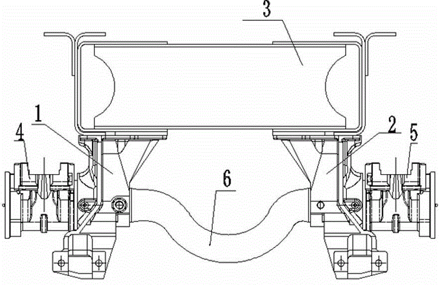
[0005] like figure 1 Shown: figure 1 The cross-sectional view of the original balance shaft assembly, including the left bracket 1 and the right bracket 2, the left bracket 1 and the right bracket 2 are set up with a vehicle frame 3, and a connecting shaft 6 is arranged between the two, and the outer two sides are respectively set. The left half shaft 4 and the right half shaft 5 jointly form a balance shaft assembly. The structure of the balance shaft assembly is relatively complicated when used, and the weight is also increased due to the use of the connecting shaft. Under the requirement of light weight, the balance shaft assembly The balance shaft assembly looks bulky

Method used


Image

  • Lightweight balance shaft assembly
  • Lightweight balance shaft assembly
  • Lightweight balance shaft assembly

Examples


Embodiment Construction

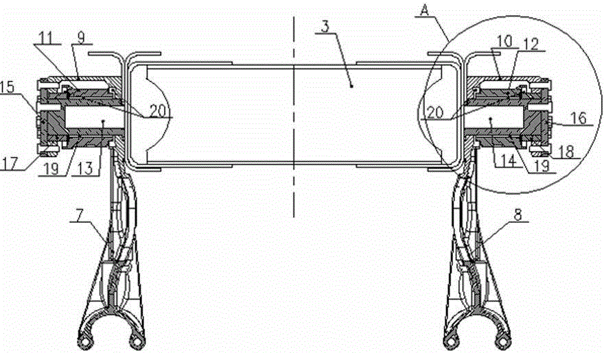
[0020] The present invention as figure 2 , 3 shown.

[0021] A lightweight balance shaft assembly, comprising a vehicle frame 3, the two outer sides of the vehicle frame 3 are erected between the left triangular bracket 7 and the right triangular bracket 8 respectively, and left bearings are arranged on the outer sides of the left triangular bracket 7 and the right triangular bracket 8 Hub assembly 9, right bearing hub assembly 10.

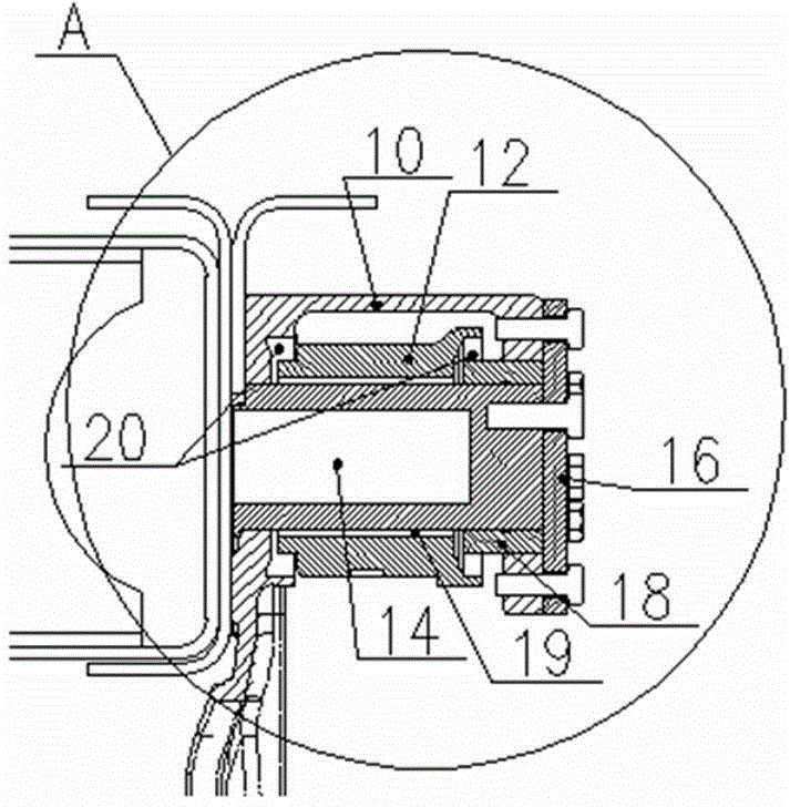
[0022] The outer rings of the left half shaft 13 and the right half shaft 14 in the left bearing hub assembly 9 and the right bearing hub assembly 10 are respectively provided with a left bearing hub 11 and a right bearing hub 12, and the left bearing hub assembly 9 and the right bearing hub The outside of the assembly 10 is fixed by the left end cover 15 and the right end cover 16; the outside of the left bearing hub assembly 9 and the right bearing hub assembly 10 are respectively provided with a left oil seal ring 17 and a right oil seal rin...


PUM


Abstract

The invention relates to a lightweight balance shaft assembly. The two edges of a vehicle frame are erected between a left triangular support and a right triangular support. The outer side of the left triangular support and the outer side of the right triangular support are provided with a left bearing hub assembly and a right bearing hub assembly. An outer ring of a left half shaft in the left bearing hub assembly and an outer ring of a right half shaft in the right bearing hub assembly are provided with a left bearing hub and a right bearing hub respectively. The outer side of the left bearing hub assembly and the outer side of the right bearing hub assembly are fixed through a left end cover and a right end cover respectively. The mode that double sealing is conducted on the inner side and outer side of oil seal and left and right sealing rings is adopted for sealing of the left bearing hub assembly and the right bearing hub assembly. The left half shaft outside the left bearing hub and the right half shaft outside the right bearing hub are further provided with nonmetal linings respectively to form a self-lubricating structure. The lightweight balance shaft assembly has stability and guarantees lightweight implementation so that the transmission shaft movement space can be increased, the lightweight balance shaft assembly is simple in structure, low in cost and light in weight, the structure is simplified, and the manufacturing difficulty is lowered.

Description

technical field [0001] The invention relates to the field of vehicles and engineering, in particular to a lightweight balance shaft assembly. Background technique [0002] The space of the drive shaft of the original balance shaft assembly is insufficient, and the weight of the whole vehicle is heavy, which is mainly reflected in several aspects: [0003] 1. Adopt the universal connecting shaft structure, which meets the limited carrying capacity and the narrow movement space of the transmission shaft; [0004] 2. Adopting a common connecting shaft structure, the weight of the balance shaft assembly is relatively heavy, the fuel consumption of the whole vehicle is high, and the cost is high, which cannot meet the current lightweight market situation. [0005] Such as figure 1 Shown: figure 1 The cross-sectional view of the original balance shaft assembly, including the left bracket 1 and the right bracket 2, the left bracket 1 and the right bracket 2 are set up with a veh...

Claims


Application Information

Patent Timeline
IPC IPC(8): B60B35/14B60B37/00
CPCY02T10/86
Inventor 程俊冉军顾康平程正波陈永炎
Owner 星源(十堰)悬架有限公司
Learn More