Welding and fixing rotary device

A technology of a rotating device and a rotating table, which is applied in the field of sheet metal processing, can solve the problems of low welding efficiency and laborious manual operation, and achieve the effects of easy welding, simple structure, and improved welding efficiency.

Inactive Publication Date: 2015-09-30
SUZHOU BIANTONG SENSING TECH
View PDF8 Cites 6 Cited by
  • Summary
  • Abstract
  • Description
  • Claims
  • Application Information

AI Technical Summary

Problems solved by technology

[0002] At present, when welding arc-shaped steel plates or steel drums, such as spot welding, since multiple points need to be welded, the steel plates or steel drums need to be rotated and moved, and the existing method is through manual handling. The steel drum is heavy, and manual operation is laborious, resulting in low welding efficiency

Method used


Image

  • Welding and fixing rotary device
  • Welding and fixing rotary device
  • Welding and fixing rotary device

Examples


Embodiment Construction

[0015] The specific implementation manner of the present invention will be described below in conjunction with the accompanying drawings.

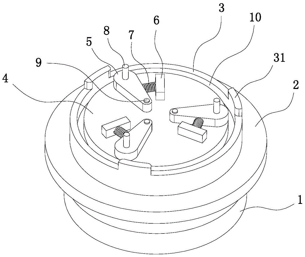
[0016] Such as Figure 1 to Figure 4 As shown, the welding fixed rotating device of this embodiment includes a base 1, a rotating table 2 and a support clamping table, the top of the base 1 is connected to the rotating table 2 by means of a central rotating shaft 11 in rotation, and the supporting clamp is affixed to the rotating table 2 stand;

[0017] The support and clamping table includes an outer stop ring 3 and an inner stop seat 4 which are centered and arranged inside and outside. The outer stop ring 3 and the inner stop seat 4 are fixed on the upper surface of the rotary table 2. There is an installation ring gap 10 between them, and the workpiece 13 is installed in the installation ring gap 10;

[0018] The upper surface of the inner block 4 is symmetrically fixed with a plurality of clamping structures, and the clamping struct...


PUM


Abstract

The invention relates to a welding and fixing rotary device. The device comprises a base, a rotary table and a supporting and clamping table. The supporting and clamping table comprises an outer blocking ring and an inner blocking base, the center of the outer blocking ring and the center of the inner blocking base coincide with each other, and the outer blocking ring and the inner blocking base are arranged on the inside and on the outside respectively. The outer blocking ring and the inner blocking base are fixedly connected to the upper surface of the rotary table, an installing annular space is arranged between the outer blocking ring and the inner blocking base, and a machined part is arranged in the installing annular space; multiple clamping structures are symmetrically and fixedly connected to the upper surface of the inner blocking base; each clamping structure comprises a clamping block rotationally connected to the inner blocking base, a fixed block fixedly connected to the upper surface of the inner blocking base and located on the side of the clamping block, and a spring connected between the clamping block and the fixed block; flanges are symmetrically arranged on the upper surface of the outer blocking ring and are matched with the clamping blocks to clamp the machined part. The device is simple in structure, the machine part can be conveniently and quickly clamped, multi-directional welding can be easily performed on the machined part, and the machined part does not need to be manually operated. Welding instability caused by manual operation is also avoided, and the effect of a welding efficiency machine is greatly improved.

Description

technical field [0001] The invention relates to the technical field of sheet metal processing, in particular to sheet metal welding equipment. Background technique [0002] At present, when welding arc-shaped steel plates or steel drums, such as spot welding, since multiple points need to be welded, the steel plates or steel drums need to be rotated and moved, and the existing method is through manual handling. The steel drum is heavy, and manual operation is laborious, resulting in low welding efficiency. Contents of the invention [0003] In view of the above-mentioned shortcomings in the welding of arc-shaped steel plates or steel drums, the applicant provides a welding fixed rotating device, which has the characteristics of simple structure and easy operation, and effectively improves the welding efficiency and effect. [0004] The technical scheme adopted in the present invention is as follows: [0005] A welding fixed rotating device, the device includes a base, a ...

Claims


Application Information

Patent Timeline
Patent Type & Authority Applications(China)
IPC IPC(8): B23K37/047B23K37/053
CPCB23K37/047B23K37/053B23K2103/04
Inventor 不公告发明人
Owner SUZHOU BIANTONG SENSING TECH
Why Eureka
Try Eureka