
a mill

A pulverizer and mill technology, which is applied in grain processing and other directions, can solve the problems of difficult cooling, large amount of returned material, affecting output, etc., and achieve the effect of extending the life of the connection, reducing the transmission of vibration, and saving production costs.

Active Publication Date: 2018-01-09
烟台方大滚塑有限公司
View PDF6 Cites 0 Cited by
  • Summary
  • Abstract
  • Description
  • Claims
  • Application Information

AI Technical Summary

Problems solved by technology

[0002] The pulverizer has been widely used as a material crushing equipment. The mill cutter head of the existing pulverizer is generally provided with a water inlet and a water outlet on the upper cover, and the upper cutter head is cooled by cooling water. If the seal is not good, Leakage is prone to occur, there is no gap between the lower cutterhead and the moving disk, and it is not easy to cool, resulting in high temperature of the lower cutterhead, which seriously affects the output; the rotating frame used is generally the middle part of the main eccentric shaft and the auxiliary eccentric shaft through the bearing seat and fixed The frame is fixed, the end is fixed with the screen rotating frame through the bearing seat, the motor and the rotating frame are fixed, the main eccentric shaft and the auxiliary eccentric shaft are connected together through a synchronous belt, and the main eccentric shaft and the auxiliary eccentric shaft work together under the drive of the motor. The synchronous rotation movement drives the rotating frame to perform a fixed swing movement around the center. Although this structure can meet the needs, due to the eccentric movement, the vibration is relatively large, and a certain amount of noise is generated. Long-term use will cause the connection to loosen and cause safety hazards. Accident; the separation sieve is composed of multi-layer screens, the screen frame is fixed from top to bottom, and the mesh number gradually increases from top to bottom. The powder that meets the requirements is screened out from the discharge port, and the powder that does not meet the requirements is discharged from the return port. Since the powder on each layer can only be screened once, the powder that meets the requirements cannot be screened out in time, and the return The amount of returned material collected by the feed port is large and the productivity is low; the counterweight structure adopted is that the counterweight block is fixed on the main shaft and the sub shaft of the rotary frame, the main shaft and the sub shaft are connected by a synchronous belt, and the motor drives the synchronous belt to make the main shaft and the sub shaft The shaft rotates synchronously. Due to the difference in installation and resistance in various aspects, the weight of the counterweight needs to be adjusted accordingly to make the rotating frame run smoothly. Different speeds of the rotating frame require different weights of the counterweight. Therefore, the counterweight structure The adjustment is more troublesome

Method used


Image

  • a mill
  • a mill
  • a mill

Examples


Embodiment 1

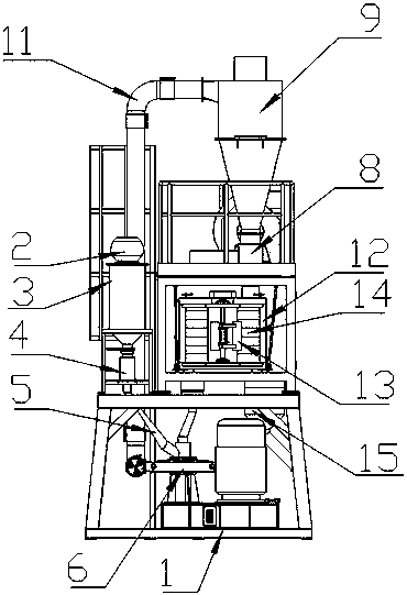
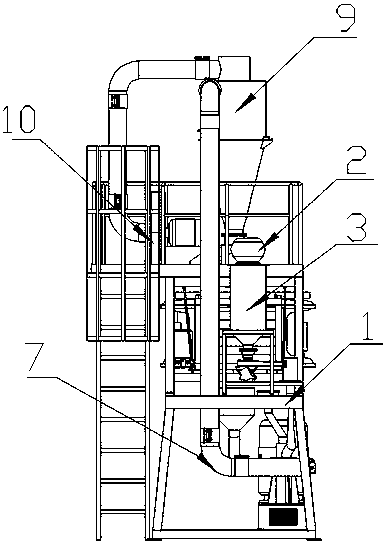
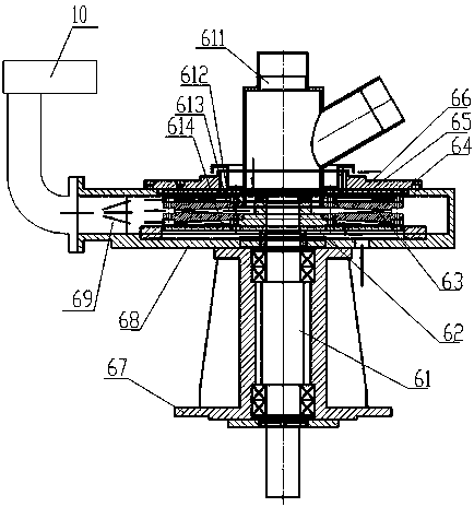
[0030] Embodiment 1, a kind of pulverizer, with reference to figure 1 , figure 2 , image 3, is that the automatic feeding machine 2, particle barrel 3, and vibrating feeder 4 connected in sequence are fixed on the frame 1, and the vibrating feeder 4 is connected to the mill 6 fixed on the frame 1 through the feeding pipe 5 The feeding port 611 of the mill 6 is connected with a suction pipe 7, and the suction pipe 7 is connected with the combined shut-off fan 8 through the cyclone separator 9, and the fan 10 fixed on the frame 1 passes through the suction pipe 11 Connect with the cyclone separator 9, the rotating frame 12 is fixed on the fixed plate on the frame 1, the main and auxiliary shafts of the rotating frame 12 are provided with a counterweight 13, the separating screen 14 is installed in the rotating frame 12, and the separating screen 14 The feed port is connected with the lower port of the combined shut-off fan 8 through a soft interface, the discharge port of th...

Embodiment 2

[0031] Embodiment 2, a kind of pulverizer, with reference to Figure 1 to Figure 6 , on the basis of Embodiment 1, the upper air channel 612 for cooling the outer side of the upper cutter head is provided with a fixed seat annular notch 615 on the fixed seat 65, and the fixed seat annular notch 615 makes the upper air channel air inlet 616 It communicates with the gap between the fixed seat 65 and the upper cutter head 64, and the gap between the fixed seat 65 and the upper cutter head 64 communicates with the upper air duct air outlet 618. The upper air duct air inlet 616 is arranged on the upper cover 66, and the fixed seat is annular. The notch 615 is arranged on the fixed seat 65 close to the main shaft 61, and the upper air channel air outlet 618 is arranged on the outer circumference of the fixed seat 65, and the middle air channel 613 used for cooling the upper cutter head and the lower cutter head is based on The feed port 611 is used as the air inlet of the middle air...

Embodiment 3

[0032] Embodiment 3, a kind of pulverizer, with reference to Figure 1 to Figure 7 , on the basis of Embodiment 2, the upper end of the suspension rod 74 is fixed on the fixed plate 71 through the joint bearing 72, and the lower end of the suspension rod 74 is fixed on the support welding plate 710 through the joint bearing 72, and the support welding plate 710 is connected with the rotating frame 12 are welded as a whole, the motor 713 is fixed on the rotating frame 12, the main shaft 76 and the auxiliary shaft 77 installed on different sides of the rotating frame 12 are installed on the rotating frame 12 through the bearing seat, and the counterweight iron 13 is installed on the main shaft 76 and the auxiliary shaft 77 , the motor 713 drives the main shaft 76 to rotate, and the main shaft 76 is connected to drive the auxiliary shaft 77 to rotate synchronously through the synchronous belt 75, and the others are exactly the same as in the second embodiment.


PUM


Abstract

The invention discloses a mill, which is composed of a frame, an automatic feeding machine, a particle material cylinder, a vibrating feeder, a feeding pipe, a mill, a fan, a material suction pipe, a cyclone separator, a combined shut-off fan, Composed of rotating frame, counterweight, separating screen and soft interface, the upper cover and the main shaft shell of the mill are respectively fixed on the upper and lower sides of the grinding disc shell, the main shaft is installed in the main shaft shell through the bearing, and the lower cutter head is installed on the movable There is a gap between the upper and lower cutter heads and the moving disk, the moving disk and the main shaft are fixed, the upper cutter head is fixed on the fixed seat, and there is a gap between the upper cutter head and the fixed seat, and the grinding disc shell is provided for cooling separately. On the outside of the upper cutter head, between the upper cutter head and the lower cutter head, on the upper air passage, the middle air passage, and the lower air passage outside the lower cutter head, the air outlet is connected to the fan, the fixing seat is connected to the upper cover, and the material inlet is connected to the fixing seat Connected, the present invention has the characteristics of adopting air cooling for the upper cutter head and the lower cutter head, stable rotation, high working efficiency, and automatic matching of eccentric loads.

Description

technical field [0001] The invention belongs to the technical field of material crushing equipment, and in particular relates to a pulverizer. Background technique [0002] The pulverizer has been widely used as a material crushing equipment. The mill cutter head of the existing pulverizer is generally provided with a water inlet and a water outlet on the upper cover, and the upper cutter head is cooled by cooling water. If the seal is not good, Leakage is prone to occur, there is no gap between the lower cutterhead and the moving disk, and it is not easy to cool, resulting in high temperature of the lower cutterhead, which seriously affects the output; the rotating frame used is generally the middle part of the main eccentric shaft and the auxiliary eccentric shaft through the bearing seat and fixed The frame is fixed, the end is fixed with the screen rotating frame through the bearing seat, the motor and the rotating frame are fixed, the main eccentric shaft and the auxili...

Claims


Application Information

Patent Timeline
Patent Type & Authority Patents(China)
IPC IPC(8): B02C18/06B02C18/16B02C23/08B02C23/00
Inventor 林宝树李旭东
Owner 烟台方大滚塑有限公司
Learn More