CT system

一种旋转部分、静止部分的技术,应用在X射线管电极、诊断、应用等方向,能够解决大结构空间设计耗费等问题,达到提高设计耗费、紧凑设计、简单结构的效果

Active Publication Date: 2015-09-30
SIEMENS HEALTHCARE GMBH
View PDF5 Cites 4 Cited by
  • Summary
  • Abstract
  • Description
  • Claims
  • Application Information

AI Technical Summary

Problems solved by technology

This requires a larger installation space and correspondingly increases the design effort

Method used


Image

  • CT system
  • CT system
  • CT system

Examples


Embodiment Construction

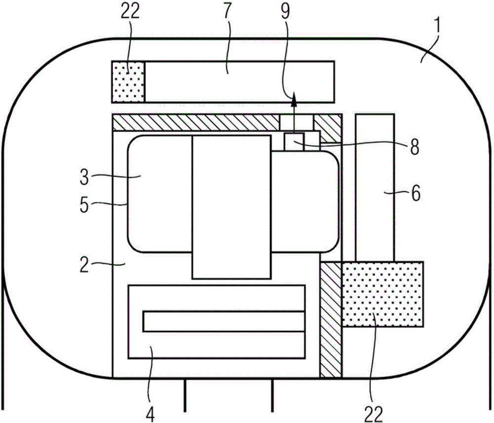
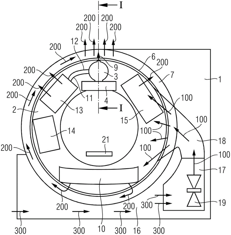
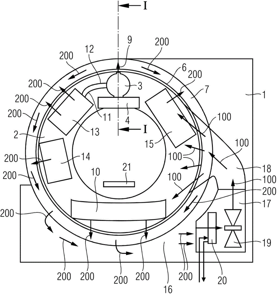
[0021] figure 1 The illustrated CT system (computerized tomography system) comprises a stationary part 1 and a rotatable part 2 which is mounted rotatably in the stationary part 1 via a rotary bearing 22 . An x-ray emitter 3 and an emitter diaphragm 4 are arranged in the rotatable part 2 . The x-ray emitter 3 has an emitter housing 5 in which an x-ray tube is arranged, which is not visible in the selected view. The X-ray tube comprises a vacuum envelope in which a cathode and an anode are arranged. Electrons generated by the cathode are accelerated in the direction of the anode and generate X-rays on reaching the anode. figure 1 X-rays not shown in X-ray emit from the X-ray emitter 3 and pass through the emitter diaphragm 4 . After leaving the emitter diaphragm 4, the X-rays emerge from the rotatable part 2 and project figure 1 Also not shown in the object to be examined (eg patient).

[0022] Heat generated inside the X-ray tube when generating X-rays is mainly absorbed ...


PUM


Abstract

The embodiments relate to a CT system with a stationary part and a rotatable part, which is supported rotatably in the stationary part. At least one x-ray tube unit cooled by a cooling fluid, an x-ray detector lying opposite the x-ray tube unit, and a cooling device coupled in terms of fluid technology to the x-ray tube unit via a coolant circuit are disposed in the rotatable part. A cooling air channel, through which cooling air is able to be fed into the rotatable part, and an exhaust air channel, through which heated exhaust air is able to be taken away from the rotatable part, are disposed in the stationary part. In accordance with the embodiments, at least one overpressure relief valve is disposed in the coolant circuit, through which the cooling fluid is able to be conveyed away in the exhaust air channel.

Description

technical field [0001] The invention relates to a CT system. Background technique [0002] Such a CT system (computed tomography system) is described in DE 10 2005 041 538 B4. Known CT systems include a stationary part and a rotatable part rotatably supported in the stationary part. Arranged in the rotatable part are at least one x-ray emitter cooled by a cooling liquid and an x-ray detector opposite the x-ray emitter as well as a cooling unit fluidically coupled to the x-ray emitter via a cooling circuit device. Cooling air ducts are arranged in the stationary part, through which cooling air can be introduced into the rotatable part. Also arranged in the stationary part are exhaust ducts, through which heated exhaust gas can be discharged from the rotatable part. [0003] The x-ray emitter has an emitter housing in which an x-ray tube is arranged. The X-ray tube includes a vacuum housing in which a cathode and an anode are arranged. Heat generated inside the X-ray tub...

Claims


Application Information

Patent Timeline
Patent Type & Authority Applications(China)
IPC IPC(8): A61B6/03
CPCH01J35/06H01J35/106H01J2235/1225G01N23/046A61B6/032A61B6/035A61B6/4488H05G1/025
Inventor H.格鲁查特卡U.库恩L.沃纳
Owner SIEMENS HEALTHCARE GMBH
Why Eureka
Try Eureka