Combustion, heat-exchange and emitter device

An emitter and device technology, applied in the field of thermal photovoltaic devices, can solve the problems of high cost and complicated manufacturing of emitter devices

Active Publication Date: 2015-09-23
TRIANGLE RESOURCE HLDG SWITZERLAND
View PDF8 Cites 0 Cited by
  • Summary
  • Abstract
  • Description
  • Claims
  • Application Information

AI Technical Summary

Problems solved by technology

However, known heat exchange and emitter devices are complex and expensive to manufacture

Method used


Image

  • Combustion, heat-exchange and emitter device
  • Combustion, heat-exchange and emitter device
  • Combustion, heat-exchange and emitter device

Examples


Embodiment approach

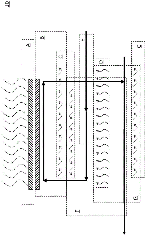
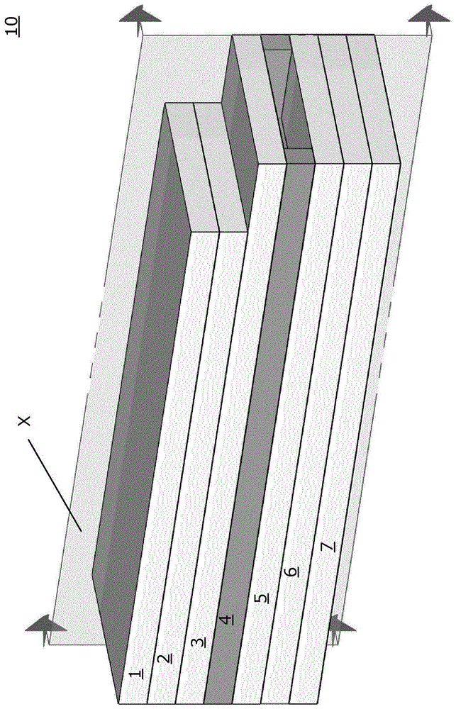
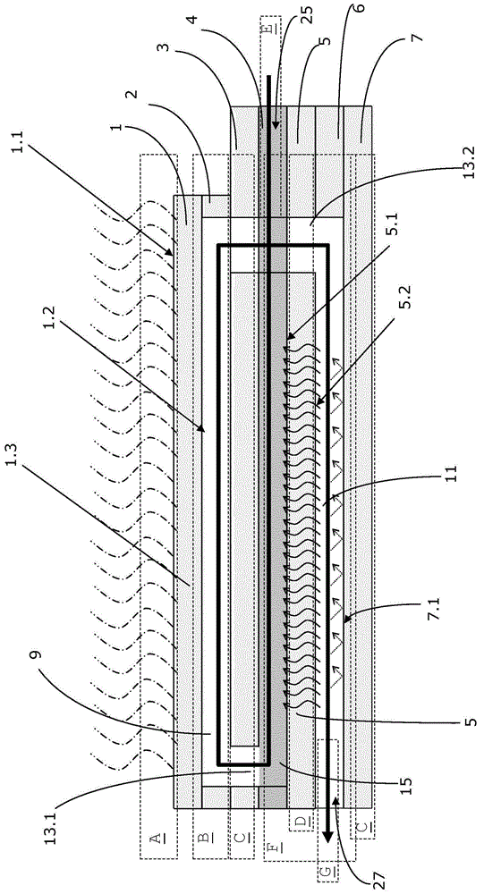
[0095] For production such as Figure 2A to Figure 3B Shown is a particularly preferred embodiment of the combustion, heat exchange and emitter device 10 of the present invention, the method further comprising the following steps:

[0096] - providing a combustion layer 2 between the emitter layer 1 and the heat conducting layer 5, the combustion layer 2 being configured and arranged to at least partially define said combustion chamber 9;

[0097] - between the emitter layer 1 and the heat conducting layer 5 is provided a further heat conduction preventing layer 3 which separates said preheating chamber 15 from the combustion chamber 9; this further heat conduction preventing layer 3 is arranged and configured to at least partially define said second flow channel 13.2, and at least partially define said first flow channel 13.1; and

[0098] - An output layer 6 is arranged between the heat conducting layer 5 and the heat conduction preventing layer 7 , the output layer 6 being...


PUM


Abstract

Combustion, heat-exchange and emitter device (10) for converting chemical into electro-magnetic radiation and method for providing such, the device (10) comprising : a radiation emission section (A) with a selective emitter (1.3) configured for emitting predominantly near-infrared radiation when heated up to high temperatures; a conversion section (B) arranged adjacent to said radiation emission section (A) and comprising a catalytic coating in order to provide for surface specific fuel combustion to maximize heat transfer between a thermal energy carrier (fuel) and the radiation emission section (A); a heat recovery section (F) configured such as to transfer excess heat of the thermal energy carrier from an exhaust outlet section (G) to an inlet section (E) such as to pre-heat the thermal energy carrier (fuel) entering the device (10) therethrough.

Description

technical field [0001] The present invention relates to a combustion, heat exchange and emitter device, a method for providing the combustion, heat exchange and emitter device, and a thermophotovoltaic device comprising the combustion, heat exchange and emitter device. Background technique [0002] Due to the need for electricity and even cleaner CO 2 With the high demand for neutral energy sources, the efficiency with which energy is harvested plays an increasingly important role. As more and more industrialized countries aim to move away from nuclear energy production, the need for alternative energy sources is greater than ever. However, to date, few, if any, actually viable alternatives are known. Many "traditional" renewable energy sources, such as wind turbines or solar power plants, have significant disadvantages which prevent their widespread spread. [0003] Still, even if these shortcomings of "traditional" renewable energy sources (such as wind turbines or sola...

Claims


Application Information

Patent Timeline
Patent Type & Authority Applications(China)
IPC IPC(8): H01L31/04F23D14/18F23D14/66F23D99/00
CPCF23D2212/005F23C2900/03001H02S10/30F23D14/66F23D91/02F23K5/20F23M2900/13004F23C13/00F23C3/00H02S10/00Y10T29/4935Y02E10/50Y02E20/34F24C3/04B23P15/00
Inventor R·霍尔茨纳U·魏德曼
Owner TRIANGLE RESOURCE HLDG SWITZERLAND
Why Eureka
Try Eureka