Centrifugal pendulum dampers and drive trains of motor vehicles
A vibration damping device, centrifugal pendulum technology, applied in the field of power transmission
- Summary
- Abstract
- Description
- Claims
- Application Information
AI Technical Summary
Problems solved by technology
Method used
Image
Examples
Embodiment Construction
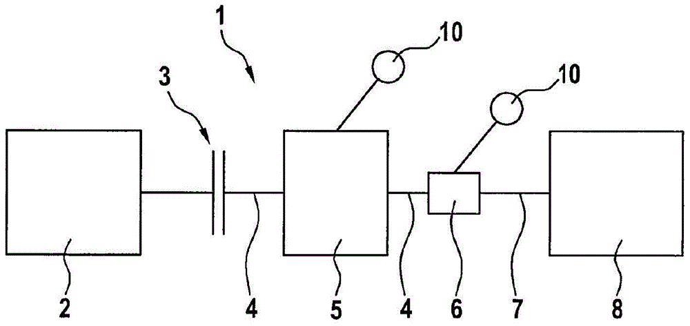
[0025] figure 1 A drive train 1 of a motor vehicle is shown schematically. The drive train has a drive device 2 , which in the exemplary embodiment presented here is an internal combustion engine. The drive device 2 is operatively or operatively connected via a separating clutch 3 to a shaft 4 of a further drive device 5 , for example an electric motor. On the side of the other drive 5 facing away from the separating clutch 3 , the shaft 4 is connected to a transmission 6 , in particular a transmission. The shaft 4 thus appears as a transmission input shaft on the side of the drive 5 facing the transmission 6 . The transmission output shaft 7 is operatively connected to at least one wheel, not shown here, of a chassis 8 of the motor vehicle. It is obvious that the torque applied to the wheels and thus the driving of the motor vehicle can be carried out either only by means of the other drive device 5 or by engaging the separating clutch 3 by means of the drive device 2 and ...
PUM
 Abstract
Description
Claims
Application Information
 - Generate Ideas
- Intellectual Property
- Life Sciences
- Materials
- Tech Scout
- Unparalleled Data Quality
- Higher Quality Content
- 60% Fewer Hallucinations
Browse by: Latest US Patents, China's latest patents, Technical Efficacy Thesaurus, Application Domain, Technology Topic, Popular Technical Reports.
© 2025 PatSnap. All rights reserved.Legal|Privacy policy|Modern Slavery Act Transparency Statement|Sitemap|About US| Contact US: help@patsnap.com


