Fall automatic power-off switch with spring reset
A spring reset and self-power-off technology, applied in electrical switches, circuits, electrical components, etc., can solve the problems of easy arcing, heating, repeated on and off, and achieve the effect of not easy to heat.
- Summary
- Abstract
- Description
- Claims
- Application Information
AI Technical Summary
Problems solved by technology
Method used
Image
Examples
Embodiment 1
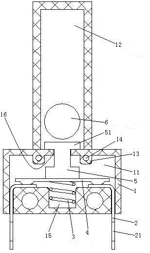
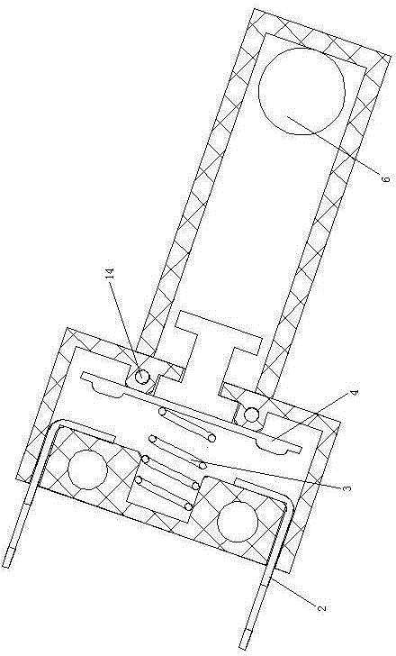
[0025] Example 1, see figure 1 , a spring-returned fall self-power-off switch, including a shell 1, a terminal pin 2, a power-off spring 3, a conductive sheet 4, a guide seat 5 and a weight 6.
[0026] The housing 1 is made of insulating material, specifically, plastic. The housing 1 is provided with an assembly cavity 11 . The upper part of the assembly cavity 11 is provided with a weight guide cavity 12 . The middle part of the bottom wall of the assembly cavity 11 is provided with a recess 15 . A pair of correcting protrusions 13 are provided on the top wall of the assembly cavity 11 . The straightening protrusions 13 are elongated structures extending in the front-rear direction (ie, the direction perpendicular to the paper surface). The straightening protrusion 13 is provided with a mounting hole 14 therein. The mounting hole 14 penetrates to the front surface of the casing 1 . A pair of correcting protrusions 13 are distributed in the left-right direction. The bot...
Embodiment 2
[0033] Embodiment two, the difference with embodiment one is:
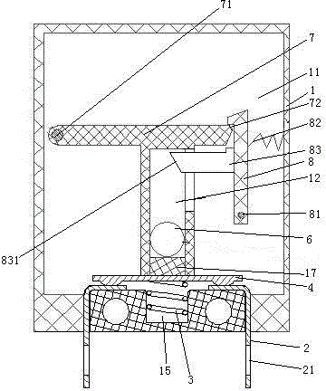
[0034] see image 3 , and also includes a swing arm 7 and a barb 8. The swing arm 7 is "T" shaped. The left end of the swing arm 7 is hinged in the assembly cavity 11 through the first hinge shaft 71 . The first hinge shaft 71 extends in the horizontal direction. The right end portion of the swing arm 7 is provided with a barb introduction surface 72 . The lower end of the swing arm 7 is fixedly connected with the conductive sheet 4 . The weight guide cavity 12 is arranged in the swing arm 7 . The lower end of the weight guide cavity 12 is provided with a shock-absorbing pad 17 . The lower end of the barb 8 is hinged in the assembly cavity 11 through the second hinge shaft 81 . The second hinge shaft 81 extends in the horizontal direction. The second hinge shaft 81 is parallel to the first hinge shaft 71 . The barb 8 is hooked on the right end of the swing arm 7 to restrict the swing arm 7 from swinging u...
PUM
 Abstract
Description
Claims
Application Information
 - R&D Engineer
- R&D Manager
- IP Professional
- Industry Leading Data Capabilities
- Powerful AI technology
- Patent DNA Extraction
Browse by: Latest US Patents, China's latest patents, Technical Efficacy Thesaurus, Application Domain, Technology Topic, Popular Technical Reports.
© 2024 PatSnap. All rights reserved.Legal|Privacy policy|Modern Slavery Act Transparency Statement|Sitemap|About US| Contact US: help@patsnap.com


