
Large-area array dynamic monitoring and measuring camera optical system

An optical system, monitoring and measurement technology, applied in optics, optical components, instruments, etc., can solve problems such as low image quality requirements, and no successful on-orbit application of fisheye imaging systems, and achieve high system stability, low distortion, The effect of reducing complexity

Active Publication Date: 2015-09-23
BEIJING RES INST OF SPATIAL MECHANICAL & ELECTRICAL TECH
View PDF5 Cites 2 Cited by
  • Summary
  • Abstract
  • Description
  • Claims
  • Application Information

AI Technical Summary

Problems solved by technology

[0005] At present, most of the fisheye lenses that have been successfully applied are in the civilian field. The image quality requirements are relatively low, and the use environment is not special. There is no fisheye imaging system that has been successfully applied in orbit.

Method used


Image

  • Large-area array dynamic monitoring and measuring camera optical system
  • Large-area array dynamic monitoring and measuring camera optical system
  • Large-area array dynamic monitoring and measuring camera optical system

Examples


Embodiment Construction

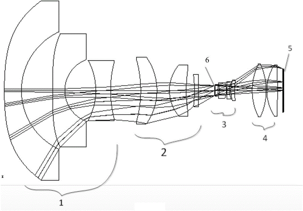
[0022] Such as figure 1 As shown, the optical system of the present invention adopts a reverse telescopic structure, including a first lens group 1, a second lens group 2, a third lens group 3, a fourth lens group 4, an area array focal plane device 5, and an aperture 6 It is placed between the second lens group and the middle third lens group to form a sub-symmetrical structure; the surveying and mapping target radiation beam that fills the entrance pupil of the optical system enters the optical system through the anti-radiation window, and passes through the front lens group 1 and the second lens group. Lens group 2 adjusts the aperture of the beam to fill the diaphragm 6, and then adjusts the angular magnification of the system through the third lens group 3 and the fourth lens group 4, so as to control the distortion of the optical system and the relative illuminance of the image plane, and the edge chief ray is incident on the image plane The angle is compressed from 65° ...


PUM


Abstract

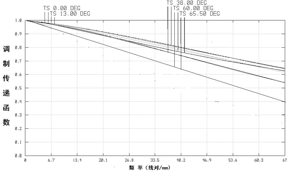
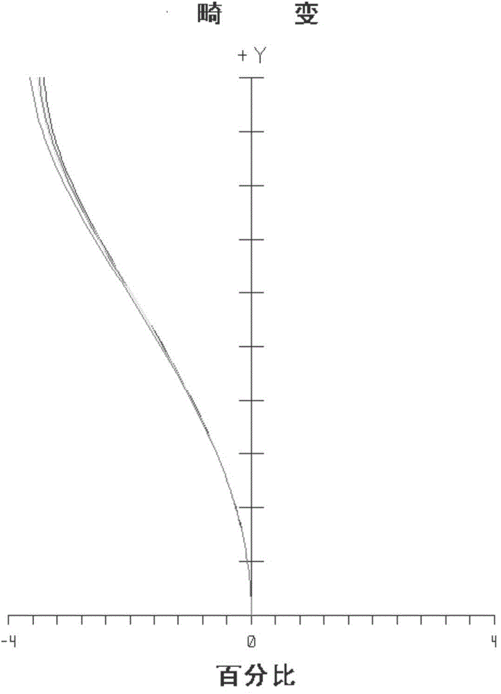
The invention relates to a large-area array dynamic monitoring and measuring camera optical system. The large-area array dynamic monitoring and measuring camera optical system is composed of anti-radiation window glass, 12 spherical lenses and a large-area array receiver; surveying and mapping target radiation beams which fully fill the entrance pupil of the optical system enters the optical system through an anti-radiation window; and an approximate telecentric optical path inverted telephoto structure is adopted to obtain low-distortion and high-illumination image information at a focal plane. According to the invention, the approximate telecentric optical system is adopted, namely, the emergent main light ray angles of fields of view are approximately parallel, and gamma is approximately equal to 0.1; a designed transfer function can achieve diffraction limits, and at the same time, can satisfy requirements for low distortion and high illumination. The large-area array dynamic-monitoring measuring camera optical system of the invention has the advantages of wide angle, being approximately telecentric, low distortion, excellent relative illumination, high engineering feasibility, high integration degree of an optical machine structure, excellent temperature adaptability and the like. The focal power of four lens groups is reasonably optimized, so that large-format, high-resolution and image plane-uniform imaging of a target scene can be realized.

Description

technical field [0001] The invention belongs to the technical field of space optical remote sensors, and relates to an area-array wide-angle surveillance camera optical imaging system applied in space under the conditions of transmission type, large field of view, approximate telecentricity, high relative illuminance, low distortion and high imaging quality. Implementation. Background technique [0002] The fisheye imaging optical system is a large field of view imaging optical system that can obtain a scene range that cannot be compared with ordinary lenses. Its application has gradually expanded from the field of special photography to the field of aerospace deep space background detection process monitoring and other fields. [0003] According to the aberration theory, the distortion of the optical system is the aberration related to the field of view, and the relative illuminance of the image surface is in the fourth power relationship with the cosine value of the angle ...

Claims


Application Information

Patent Timeline
Patent Type & Authority Applications(China)
IPC IPC(8): G02B13/06G02B13/22G02B13/18G02B13/00
CPCG02B13/0045G02B13/04G02B13/06G02B13/18G02B13/22
Inventor 汤天瑾佟静波张宏伟
Owner BEIJING RES INST OF SPATIAL MECHANICAL & ELECTRICAL TECH
Learn More