
Constrained tomography speed modeling method based on reverse ray tracing

A technology of ray tracing and velocity modeling, applied in the field of geophysical exploration, which can solve the problems of limited viewing angle, high sensitivity and limited application range

Inactive Publication Date: 2015-09-23
CHINA PETROLEUM & CHEM CORP +1
View PDF6 Cites 11 Cited by
  • Summary
  • Abstract
  • Description
  • Claims
  • Application Information

AI Technical Summary

Problems solved by technology

However, limited by its theory, ray tomography can only pass through a limited part of the object, and is highly sensitive to limited viewing angles. It usually requires that the wave velocity change is small within a wavelength range, and the scale of the inhomogeneous body is comparable to the seismic wavelength. The ratio is much larger, and the medium model is required to be smooth, which limits its application range

Method used


Image

  • Constrained tomography speed modeling method based on reverse ray tracing
  • Constrained tomography speed modeling method based on reverse ray tracing
  • Constrained tomography speed modeling method based on reverse ray tracing

Examples


Embodiment Construction

[0029] In order to make the above and other objects, features and advantages of the present invention more comprehensible, preferred embodiments are listed below and described in detail in conjunction with the accompanying drawings.

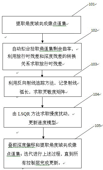
[0030] like figure 1 as shown, figure 1 It is a flow chart of the constrained tomographic velocity modeling method based on reverse ray tracing of the present invention.

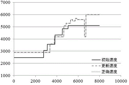
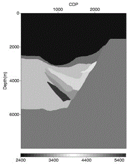
[0031] In step 101, an angle-domain common image point gather is extracted. The velocity model obtained by conventional velocity analysis is used as the initial velocity model (such as figure 2 ), using the undulating surface Gaussian beam migration for migration imaging (eg image 3 ) and extract the common image point gather in the angle domain (such as Figure 4 ). figure 2 It is a schematic diagram of the initial velocity field of the conglomerate body model in an embodiment of the present invention; the superimposed velocity field in the time domain is obtained base...


PUM


Abstract

The invention provides a constrained tomography speed modeling method based on reverse ray tracing. The constrained tomography speed modeling method based on reverse ray tracing comprises the steps of: extracting angle domain common image gathers; automatically fitting the residual curvature of the extracted angle gathers, and calculating a travel time residual by means of a conversion relationship between the travel time residual and a depth residual; by means of a reverse ray tracing method, recording a ray arc length, and calculating a sensitivity matrix; calculating a slow degree disturbance and updating a speed model; and stacking the front depth migration and the extracted angle domain common image gathers, iterating the steps until all controlled layers are updated. The constrained tomography speed modeling method based on reverse ray tracing realizes high migration speed analysis efficiency and high precision in waveform inversion. On condition that a waveform inversion technique cannot be applied in practice, tomography speed inversion has certain advantages and theoretical advantages as a speed updating method.

Description

technical field [0001] The invention relates to the field of geophysical exploration, in particular to a constrained tomographic velocity modeling method based on reverse ray tracing. Background technique [0002] Tomography was first used in medicine and was introduced into the field of applied geophysics in the early 1980s. It mainly studies how to use seismic waves, electromagnetic waves or other field data to image the interior of the earth. It has entered the practical stage since the 1990s. [0003] The theoretical basis of tomography is Radon transform, that is, u(ρ,θ)=∫ L f(x,y)ds. From the perspective of image reconstruction inside an object, an image of a slice of an object is a function of two spatial variables x, y, called an image function, denoted as f(x, y); "irradiate" the object with incident waves in different directions , the observed wave field information is at least a function of two variables, the incident wave direction θ and the position of the obs...

Claims


Application Information

Patent Timeline
IPC IPC(8): G01V1/50
Inventor 芮拥军滕厚华张凯单联瑜王延光尚新民冮明川苗永康
Owner CHINA PETROLEUM & CHEM CORP
Learn More