


Quick Research
Generate reliable direction feasibility study reports for your R&D in just a few steps.

Technical Q&A
Discover and master advanced knowledge NOW. Basics, ideas, possibilities, all at once.

Find Solutions
As an expert in R&D theories, this can generate solutions to your technical problems instantly.

Evaluate Feasibility
Analyze your overall solution with one click, know your potential R&D risks in advance.

Monitor Landscape
Get weekly tech updates, stay abreast of the latest tech innovations and key insights.
Method for compensating amplitude of emission signal of broadband sonar system
A technology for transmitting signals and acoustic signals, which is applied in the field of compensating the amplitude of the transmitted signal of a broadband sonar system, and can solve the problems of increasing the design difficulty of the transmitting system and the difficulty of high-order matching circuits.
- Summary
- Abstract
- Description
- Claims
- Application Information
AI Technical Summary
Problems solved by technology
Method used
Image


Examples
specific Embodiment approach 1
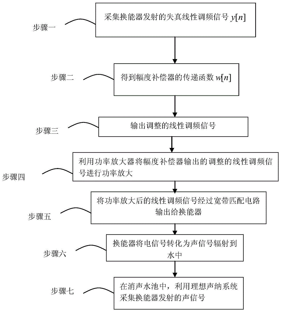
[0089] Specific implementation mode 1: The method for compensating the amplitude of the signal transmitted by the broadband sonar system of this embodiment is specifically prepared according to the following steps:
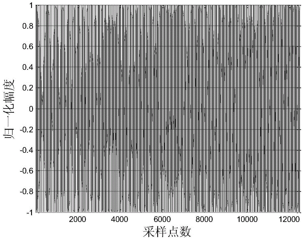
[0090] Step 1. The sonar launch system transmits the ideal chirp signal x 0 [n] As shown in Figure 3(a) and Figure 3(b), in the anechoic pool, the ideal sonar receiving system is used to collect the distorted chirp signal y[n] emitted by the transducer as shown in Figure 5(a) and Figure 5. (b); Among them, the sonar emission system is composed of an ideal signal source, a power amplifier, a broadband matching circuit and a transducer. The bandwidth of the ideal chirp signal is the working bandwidth of the sonar emission system. The specific components and connections are as follows figure 2 As shown, the amplitude-frequency response of the broadband matching circuit and the transducer is as Figure 4 Shown
[0091] Step 2: Combine the distorted chirp signal y[n] with t...
specific Embodiment approach 2
[0097] Specific embodiment two: this embodiment is different from specific embodiment one in that in step one, the sonar emission system transmits the ideal chirp signal x 0 [n] As shown in Figure 3(a) and Figure 3(b), in the anechoic pool, the ideal sonar receiving system is used to collect the distorted chirp signal y[n] emitted by the transducer. The specific process:
[0098] (1) The ideal chirp signal is amplified by the power amplifier;
[0099] (2) The amplified ideal chirp signal is output to the transducer through the broadband matching circuit;
[0100] (3) The transducer converts the electrical signal into an acoustic signal (distorted chirp signal) and radiates into the water;
[0101] (4) The ideal sonar system uses the collector to collect the distorted chirp signal emitted by the transducer in the water as shown in Figure 5(a) and Figure 5(b);
[0102] The ideal sonar receiving system uses standard hydrophones and measurement amplifiers to process the received acoustic si...
specific Embodiment approach 3
[0103] Specific implementation manner 3: The other steps of this implementation manner are the same as those of specific implementation manners 1 or 2, except that the broadband matching network design process in step 1 is specifically:
[0104] (1) Use an impedance analyzer to test the input impedance data Z of the transducer l (s);
[0105] (2) Using impedance data Z l (s) Calculate the output impedance function Z of the matching network q (s);
[0106] (3) According to Z q (s) The calculated implementation structure and parameters of the broadband matching network. Other steps and parameters are the same as those in the first or second embodiment.
PUM
 Abstract
Description
Claims
Application Information
 - R&D Engineer
- R&D Manager
- IP Professional
- Industry Leading Data Capabilities
- Powerful AI technology
- Patent DNA Extraction
Browse by: Latest US Patents, China's latest patents, Technical Efficacy Thesaurus, Application Domain, Technology Topic, Popular Technical Reports.
© 2024 PatSnap. All rights reserved.Legal|Privacy policy|Modern Slavery Act Transparency Statement|Sitemap|About US| Contact US: help@patsnap.com