Hydraulic system of vibrating pile driver

A technology of vibrating pile driver and hydraulic system, applied in sheet pile wall, mechanical equipment, fluid pressure actuating device, etc., can solve the problems of high performance requirements of oil cylinder, inconvenient transportation and use, complicated structure of hydraulic system, etc. The effect of low manufacturing cost, simple structure and high reliability

Active Publication Date: 2015-09-23
SUZHOU XINENG ENVIRONMENTAL SCI & TECH CO LTD
View PDF9 Cites 4 Cited by
  • Summary
  • Abstract
  • Description
  • Claims
  • Application Information

AI Technical Summary

Problems solved by technology

[0002] Due to the large driving force and stable movement of the hydraulic system, hydraulic pile drivers are often used in piling now, but the commonly used hydraulic pile drivers all use the principle of static pressure, that is, use a pile driver with a large enough weight against the pressure of the oil cylinder. Pile parts are pressed in. This kind of working principle requires high performance of the oil cylinder, and the reaction force during piling is large, which is easy to damage the machine. The hydraulic system of this type of pile driver has a complex structure, high manufacturing cost and high maintenance cost. And the volume is very large, it is inconvenient to transport and use

Method used


Image

  • Hydraulic system of vibrating pile driver
  • Hydraulic system of vibrating pile driver
  • Hydraulic system of vibrating pile driver

Examples


Embodiment Construction

[0016] The present invention will be described in further detail below in conjunction with the accompanying drawings.

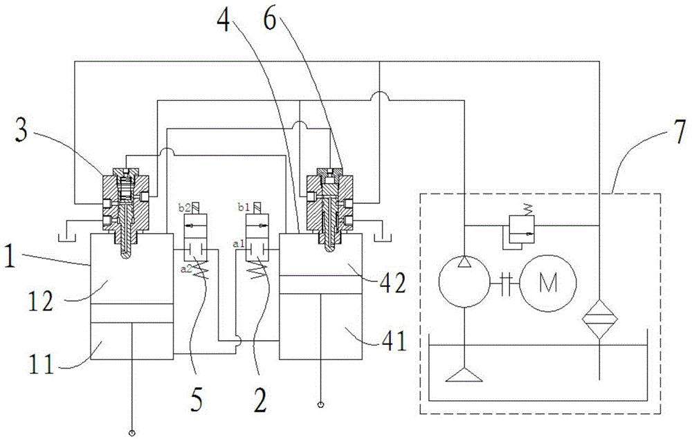
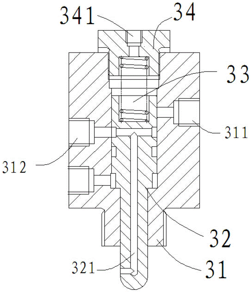
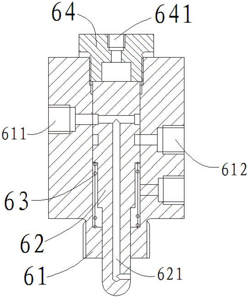
[0017] refer to figure 1 — Figure 4 , Vibration pile driver hydraulic system, including the first cylinder 1, the first electromagnetic valve 2, the first vibration control valve 3, the second cylinder 4, the second electromagnetic valve 5, the second vibration control valve 6 and the drive mechanism 7. Among them, the first vibration control valve 3 is connected with the first oil cylinder 1, the second vibration control valve 6 is connected with the second oil cylinder 4, the first electromagnetic valve 2 and the second electromagnetic valve 5 are connected with the first oil cylinder 1 at one end, and the other end is connected with the first oil cylinder 1. It is connected with the second oil cylinder 4 , and both the first vibration control valve 3 and the second vibration control valve 6 are connected with the driving mechanism 7 .

[0018] The first...


PUM


Abstract

The invention discloses a hydraulic system of a vibrating pile driver. The hydraulic system comprises a first oil cylinder, a first electromagnetic valve, a first vibration control valve, a second oil cylinder, a second electromagnetic valve, a second vibration control valve and a driving mechanism. The first vibration control valve is connected with the first oil cylinder, and the second vibration control valve is connected with the second oil cylinder; one end of the first electromagnetic valve and one end of the second electromagnetic valve are connected with the first oil cylinder, and the other end of the first electromagnetic valve and the other end of the second electromagnetic valve are connected with the second oil cylinder; and the first vibration control valve and the second vibration control valve are both connected with the driving mechanism. The electromagnetic valves and the vibration control valves are utilized for controlling the working sequence of the first oil cylinder and the second oil cylinder, and therefore the two oil cylinders constantly and alternatively vibrate for pile driving; on the basis of the pile driving principle, the impact fore is large, too large pile driving mass is not needed, the reactive force is small, and the reliability is high; and in addition, the full-hydraulic system is adopted to carry out driving and control, and the hydraulic system is simple in structure, large in driving force, convenient to control and use, and also low in manufacturing cost.

Description

technical field [0001] The invention relates to the field of driving and control systems of pile drivers, in particular to a hydraulic system of a vibrating pile driver. Background technique [0002] Due to the large driving force and stable movement of the hydraulic system, hydraulic pile drivers are often used in piling now, but the commonly used hydraulic pile drivers all use the principle of static pressure, that is, use a pile driver with a large enough weight against the pressure of the oil cylinder. Pile parts are pressed in. This kind of working principle requires high performance of the oil cylinder, and the reaction force during piling is large, which is easy to damage the machine. The hydraulic system of this type of pile driver has a complex structure, high manufacturing cost and high maintenance cost. And the volume is very large, and it is not convenient to transport and use. Contents of the invention [0003] The object of the present invention is to provid...

Claims


Application Information

Patent Timeline
Patent Type & Authority Applications(China)
IPC IPC(8): F15B13/06E02D7/18
CPCE02D7/18F15B13/07
Inventor 吴家集黄共才
Owner SUZHOU XINENG ENVIRONMENTAL SCI & TECH CO LTD
Why Eureka
Try Eureka