Negative pressure drug dissolver
A drug dissolving device and negative pressure technology, which is applied in the field of negative pressure drug dissolving device, can solve the problems of high manufacturing cost and complex structure of the syringe, and achieve the effects of eliminating pollution, reducing the clinical treatment effect, and avoiding the waste of drugs
- Summary
- Abstract
- Description
- Claims
- Application Information
AI Technical Summary
Problems solved by technology
Method used
Image
Examples
Embodiment 1
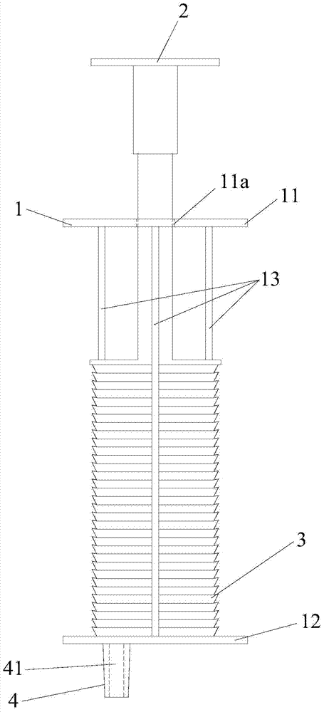
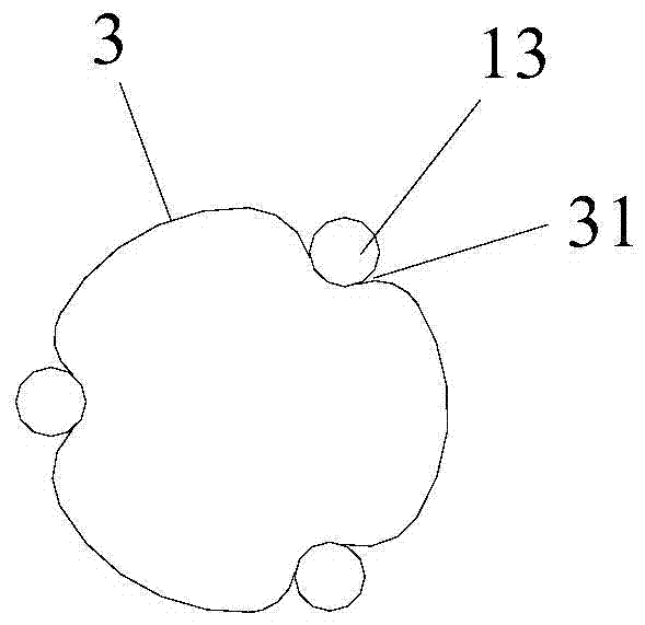
[0027] Please refer to figure 1 and figure 2 , the negative pressure drug dissolver includes a bracket 1, a push rod 2, a telescopic tube 3 that can be stretched longitudinally and a needle holder 4.
[0028] The bracket 1 includes an upper positioning plate 11 and a lower positioning plate 12 , and a limiting structure 13 connected between the upper positioning plate 11 and the lower positioning plate 12 . The upper positioning plate 11 is provided with a limiting hole 11a. The limiting structure 13 is three guide rods. The surface of one of the guide rods on the support 1 is provided with a scale, so that it is convenient to check the capacity of the medicinal solution in the negative pressure drug dissolver.
[0029] The push rod 2 is installed at the limiting hole 11a.
[0030] The telescopic tube 3 is an organ type telescopic tube, and is made of medical plastic material. The telescopic tube 3 is located between the upper positioning plate 11 and the lower positioni...
Embodiment 2
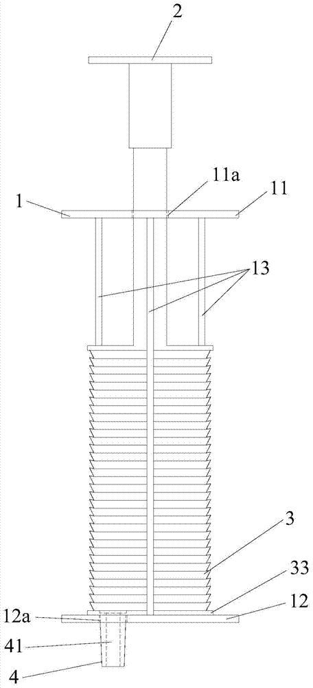
[0034] Please refer to figure 2 and image 3 , the negative pressure drug dissolver includes a bracket 1, a push rod 2, a telescopic tube 3 that can be stretched longitudinally and a needle holder 4.
[0035] The bracket 1 includes an upper positioning plate 11 and a lower positioning plate 12 , and a limiting structure 13 connected between the upper positioning plate 11 and the lower positioning plate 12 . The upper positioning plate 11 is provided with a limiting hole 11a. The lower positioning plate 12 is provided with a through hole 12a. The limiting structure 13 is three guide rods. The surface of one of the guide rods on the support 1 is provided with a scale, so that it is convenient to check the capacity of the medicinal solution in the negative pressure drug dissolver.
[0036] The push rod 2 is installed at the limiting hole 11a.
[0037] The telescopic tube 3 is an organ type telescopic tube, and is made of medical plastic material. The telescopic tube 3 is l...
Embodiment 3
[0041] Please refer to Figure 4 , the negative pressure drug dissolver includes a bracket 1, a push rod 2, a telescopic tube 3 that can be stretched longitudinally and a needle holder 4.
[0042] The bracket 1 includes an upper positioning plate 11 and a lower positioning plate 12 , and a limiting structure 13 connected between the upper positioning plate 11 and the lower positioning plate 12 . The upper positioning plate 11 is provided with a limiting hole 11a. The position-limiting structure 13 is a cylindrical tube, and the cylindrical tube, the upper positioning plate 11 and the lower positioning plate 12 form a closed cylindrical structure. The surface of the cylindrical barrel is provided with a scale, so that it is convenient to check the capacity of the medicinal solution in the negative pressure drug dissolver.
[0043] The push rod 2 is installed at the limiting hole 11a.
[0044] The telescopic tube 3 is an organ type telescopic tube, and is made of medical plas...
PUM
 Abstract
Description
Claims
Application Information
 - R&D Engineer
- R&D Manager
- IP Professional
- Industry Leading Data Capabilities
- Powerful AI technology
- Patent DNA Extraction
Browse by: Latest US Patents, China's latest patents, Technical Efficacy Thesaurus, Application Domain, Technology Topic, Popular Technical Reports.
© 2024 PatSnap. All rights reserved.Legal|Privacy policy|Modern Slavery Act Transparency Statement|Sitemap|About US| Contact US: help@patsnap.com


