Rocket engine, rocket, and method for starting rocket engine
A rocket engine and turbine technology, which is applied to rocket engine devices, engine functions, machines/engines, etc., can solve the problems of high cost, exhaust of combustion gas, and large energy loss, so as to reduce energy loss, improve combustion efficiency, The effect of improving robustness
- Summary
- Abstract
- Description
- Claims
- Application Information
AI Technical Summary
Problems solved by technology
Method used
Image
Examples
no. 1 Embodiment approach
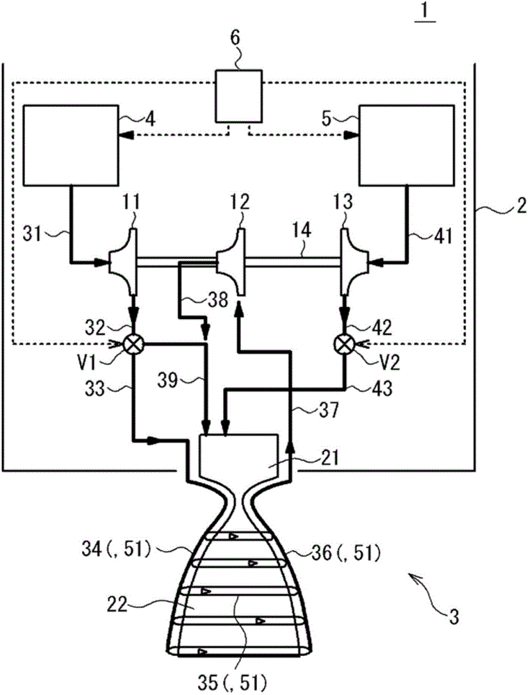
[0030] The structure of the rocket engine of the first embodiment and a rocket to which it is applied will be described. figure 2 It is a schematic diagram showing the structure of the rocket engine of this embodiment and the rocket to which it is applied. Rocket 1 flies by burning hydrocarbon fuel and oxidizer, and ejecting combustion gas backward. The rocket 1 has a rocket body 2 and a rocket engine 3 .
[0031] The rocket body 2 includes a fuel tank 4 , an oxidizing agent tank 5 , and a control unit 6 . The fuel tank 4 stores liquid hydrocarbon fuel. The fuel tank 4 delivers fuel to the rocket engine 3 by means of gas pressurization or the like based on the control of the control unit 6 . The oxidizing agent tank 5 stores a liquid oxidizing agent (for example: LOX). The oxidant tank 5 sends oxidant to the rocket engine 3 by means of gas pressurization or the like based on the control of the control unit 6 . The control unit 6 is an information processing device such a...
no. 2 Embodiment approach
[0059] The structure of the rocket engine of the second embodiment and the rocket to which it is applied will be described. This embodiment differs from the first embodiment in that the catalyst portion is provided separately instead of the piping of the fuel flow path. Hereinafter, differences will be mainly described.
[0060] Figure 5 It is a schematic diagram showing the structure of the rocket engine of this embodiment and the rocket to which it is applied. In the rocket engine 3 a of the present embodiment, the catalyst unit 52 is provided separately as a catalytic reactor in the middle of the fuel flow path 37 , not in at least part of the piping of the fuel flow path 34 to the fuel flow path 36 . In other words, in the first embodiment, the catalyst part 51 is the fuel flow path 34 to the fuel flow path 36, which are also the catalyst part 51, but in this embodiment, the catalyst part 52 is an independent catalytic reactor, and is provided in the fuel flow path. on...
PUM
 Abstract
Description
Claims
Application Information
 - R&D Engineer
- R&D Manager
- IP Professional
- Industry Leading Data Capabilities
- Powerful AI technology
- Patent DNA Extraction
Browse by: Latest US Patents, China's latest patents, Technical Efficacy Thesaurus, Application Domain, Technology Topic, Popular Technical Reports.
© 2024 PatSnap. All rights reserved.Legal|Privacy policy|Modern Slavery Act Transparency Statement|Sitemap|About US| Contact US: help@patsnap.com


