Palmprint recognition circuit based on LTPS technology and palmprint recognition method thereof and display screen

A technology of palmprint recognition and palmprint, which is applied in the field of information recognition, can solve the problems of no palmprint recognition circuit and method, and achieve the effect of eliminating the change of parasitic capacitance

Active Publication Date: 2015-09-16
BOE TECH GRP CO LTD +1
View PDF5 Cites 12 Cited by
  • Summary
  • Abstract
  • Description
  • Claims
  • Application Information

AI Technical Summary

Benefits of technology

In this patented system, we propose create a way to recognize different patterns made up from shiny areas on your fingers or other parts when they are touch typing with electronic devices like tablets. These differences can be used to identify any specific characters called them - these variations help us improve our ability to distinguish between genuine ones and false alarms.

Problems solved by technology

This patented technical problem addressed by this patents relates to developing a type of electronic device that recognizes patterns from finger prints or other objects like pins without changing their appearance over time due to changes caused during human activities.

Method used


Image

  • Palmprint recognition circuit based on LTPS technology and palmprint recognition method thereof and display screen
  • Palmprint recognition circuit based on LTPS technology and palmprint recognition method thereof and display screen
  • Palmprint recognition circuit based on LTPS technology and palmprint recognition method thereof and display screen

Examples


Embodiment Construction

[0042] The specific implementation of the present invention will be described in detail below in conjunction with the accompanying drawings and specific embodiments.

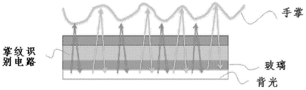
[0043] refer to figure 1 , figure 1 is a schematic diagram showing a stacked structure including a palmprint recognition circuit based on LTPS technology according to an embodiment of the present invention. In this laminated structure, it includes a backlight layer, a glass layer, a palmprint recognition circuit layer, and the like from bottom to top. When the user places the palm above the upper surface of the laminated structure, the light emitted by the backlight layer is reflected by the obvious line features (eg, ridges and valleys) on the palm, and reaches the palmprint recognition circuit. The palmprint recognition circuit recognizes the palmprint by detecting the light intensity difference between the valley line and the ridge line. For the valley lines, the light emitted by the backlight layer is total...


PUM


Abstract

The invention provides a palmprint recognition circuit based on an LTPS technology and a palmprint recognition method thereof and a display screen. The palmprint recognition circuit comprises an optical signal collection unit, a current signal amplification unit and a current signal detection unit. The optical signal collection unit collects optical signals indicating palmprint information and converts the collected optical signals into current signals. The optical signals are acquired from light emitted by backlight through reflection of the palmprint of a user palm. The current signal amplification unit is connected with the optical signal collection unit and used for amplifying the converted current signals. The current signal detection unit is connected with the current signal amplification unit and used for detecting intensity of the amplified current signals. The intensity of the current signals indicates the ridge lines or the valley lines of the palmprint in the palmprint information. Therefore, the technology gap of no palmprint recognition circuit or method aiming at an LTPS-TFT display panel in the market is solved, and influence on the recognition result caused by change of parasitic capacitance generated by change of a circuit process varied wiring mode in the recognition process is also eliminated.

Description


Claims


Application Information

Patent Timeline
Owner BOE TECH GRP CO LTD
Why Eureka
Try Eureka