
Airplane auxiliary fuel tank flutter model

A flutter model and auxiliary fuel tank technology, which is applied in the field of aviation testing, can solve the problems of inconvenient stiffness adjustment, difficult coupling of pitch and yaw modes, and the influence of aircraft flutter characteristics is not considered, so as to achieve the effect of saving test costs and time.

Active Publication Date: 2015-09-16
XIAN AIRCRAFT DESIGN INST OF AVIATION IND OF CHINA
View PDF5 Cites 5 Cited by
  • Summary
  • Abstract
  • Description
  • Claims
  • Application Information

AI Technical Summary

Problems solved by technology

[0003] In the past, the stiffness of the three directions of the auxiliary fuel tank was simulated in the form of a composite beam frame, and there were problems such as difficult identification of pitch and yaw modal coupling, and inconvenient stiffness adjustment.
Moreover, the auxiliary fuel tank flutter model only uses counterweights to simulate the mass and inertia characteristics of the auxiliary fuel tank, and does not consider the influence of fuel sloshing in the auxiliary fuel tank on the flutter characteristics of the aircraft, which often leads to inaccurate test results.

Method used


Image

  • Airplane auxiliary fuel tank flutter model
  • Airplane auxiliary fuel tank flutter model
  • Airplane auxiliary fuel tank flutter model

Examples


Embodiment Construction

[0027] Reference will now be made in detail to the exemplary embodiments, examples of which are illustrated in the accompanying drawings. When the following description refers to the accompanying drawings, the same numerals in different drawings refer to the same or similar elements unless otherwise indicated.

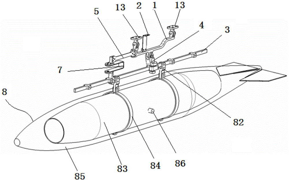
[0028] Such as figure 1 and figure 2 As shown, the aircraft auxiliary fuel tank flutter model provided by the present invention includes a general pylon beam 1, a special pylon beam 3, an auxiliary fuel tank model 8, and a side flat spring plate 2, a rotating arm 4, and a yaw spring arranged between them Sheet 5 and pitch spring sheet 7 and other components.

[0029] The universal hanger beam 1 can adopt various suitable structures, and has protruding first fixing parts 11 and second fixing parts 12 at the top surfaces of both ends of the universal hanger beam 1 along the direction perpendicular to the axis of the universal hanger beam 1 . Wherein, one end of the f...


PUM


Abstract

The invention relates to the field of aviation tests, particularly relates to an airplane auxiliary fuel tank flutter model, and at least can solve problems of difficult identification for pitch and yaw modal coupling and inconvenient stiffness adjustment existing in a flutter model at present. In the airplane auxiliary fuel tank flutter model provided by the invention, decoupling is carried out on the stiffness of an auxiliary fuel tank model in three directions, thereby being convenient for identifying such three modals as lateral balancing, yawing and pitching in a test. In addition, frequencies of the three modals of lateral balancing, pitching and yawing of the auxiliary fuel tank are simulated respectively through three correspondingly arranged replaceable spring pieces. The frequency of a certain modal of the auxiliary fuel tank can further be adjusted through replacing the spring piece, thereby being convenient for carrying out frequency adjustment in allusion to the auxiliary fuel tank model in the test, and saving the test cost and the test time.

Description

technical field [0001] The invention relates to the field of aviation tests, in particular to an aircraft auxiliary fuel tank flutter model. Background technique [0002] In order to prolong the flight time, aircraft often hang auxiliary fuel tanks under the wings. However, the setting of auxiliary fuel tanks will have a great impact on the flutter characteristics of the aircraft; therefore, in order to study the impact of auxiliary fuel tanks on the ground, the wind tunnel test method is currently used , and the auxiliary fuel tank is simulated by the auxiliary fuel tank flutter model; when designing this type of aircraft flutter model, it is required to simulate three modes of the auxiliary fuel tank side level, pitch and yaw according to the requirements. [0003] In the past, the stiffness of the three directions of the auxiliary fuel tank was simulated in the form of a composite beam frame, and there were problems such as difficult identification of pitch and yaw modal ...

Claims


Application Information

Patent Timeline
IPC IPC(8): G01M9/08
Inventor 马翔张红波陈海
Owner XIAN AIRCRAFT DESIGN INST OF AVIATION IND OF CHINA
Learn More