
A garbage incineration device

A garbage incineration and unified technology, applied in the field of machinery, can solve the problems of garbage accumulation, incomplete incineration of garbage, slow incineration efficiency, etc., and achieve the effect of saving water resources

Active Publication Date: 2017-07-25
冯必敖
View PDF7 Cites 0 Cited by
  • Summary
  • Abstract
  • Description
  • Claims
  • Application Information

AI Technical Summary

Problems solved by technology

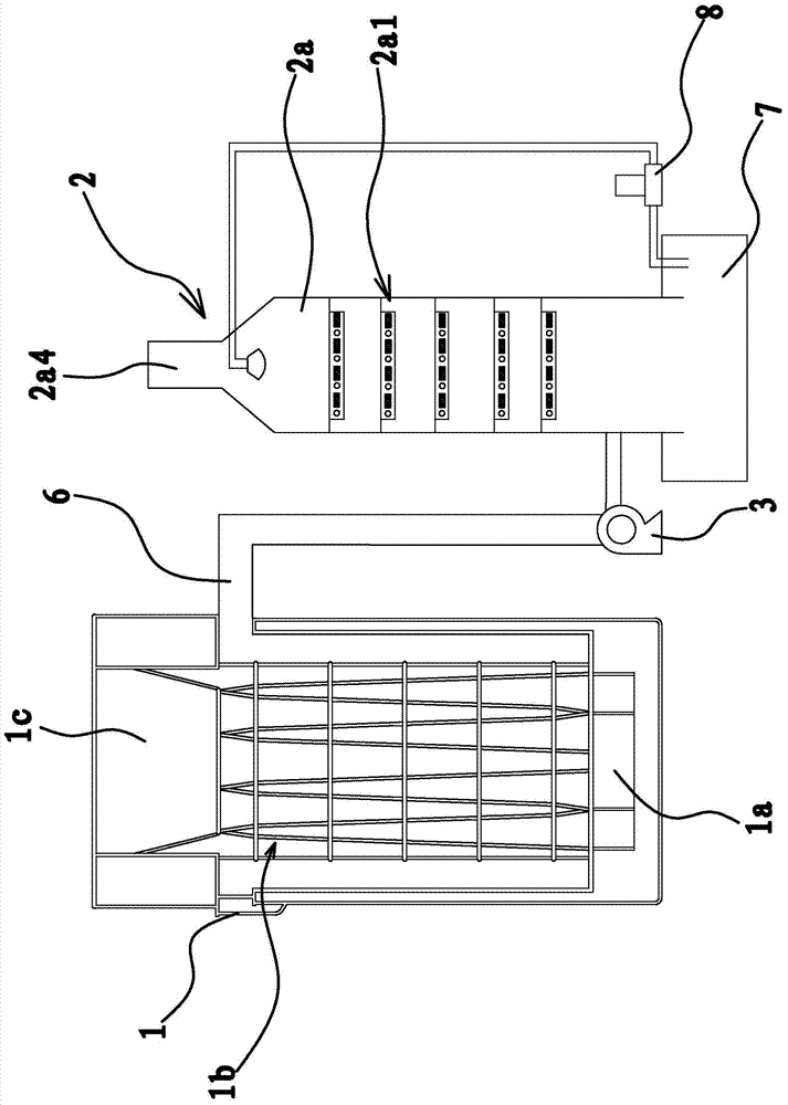
[0004] Although the garbage incinerator can effectively treat the toxic gas in the flue gas produced by garbage incineration by adding a smoke processor, thereby reducing the emission of toxic gas and achieving the purification effect, but this garbage incinerator also has obvious problems. Disadvantages: Since the cold water pipe is installed on the side wall and bottom of the furnace body, when the garbage is put into the furnace body for incineration, the flame can only be incinerated from the bottom of the garbage, which will easily cause the incineration speed of the garbage to be slow, and because of The cold water pipes installed on the side wall of the furnace body are arranged in a circular shape, and only the garbage near the cold water pipes can be incinerated, while the garbage in the middle will be directly thrown into the bottom of the furnace body. Due to the slow incineration efficiency, it will eventually lead to waste It cannot be completely incinerated in the furnace body, resulting in the accumulation of garbage in the furnace body

Method used


Image

  • A garbage incineration device
  • A garbage incineration device
  • A garbage incineration device

Examples


Embodiment 1

[0034] Such as figure 1 As shown, a garbage incineration device includes a cylindrical tower body 1 with a hollow inner cavity, a smoke processor 2, and an induced draft fan 3 arranged between the tower body 1 and the smoke processor 2. The induced draft fan 3 The air inlet and the air outlet are respectively connected to the tower body 1 and the smoke processor 2. The bottom of the inner cavity of the tower body 1 is provided with a combustion chamber 1a. The garbage disposal port 1c is open and communicated with the inner cavity of the tower body 1 .

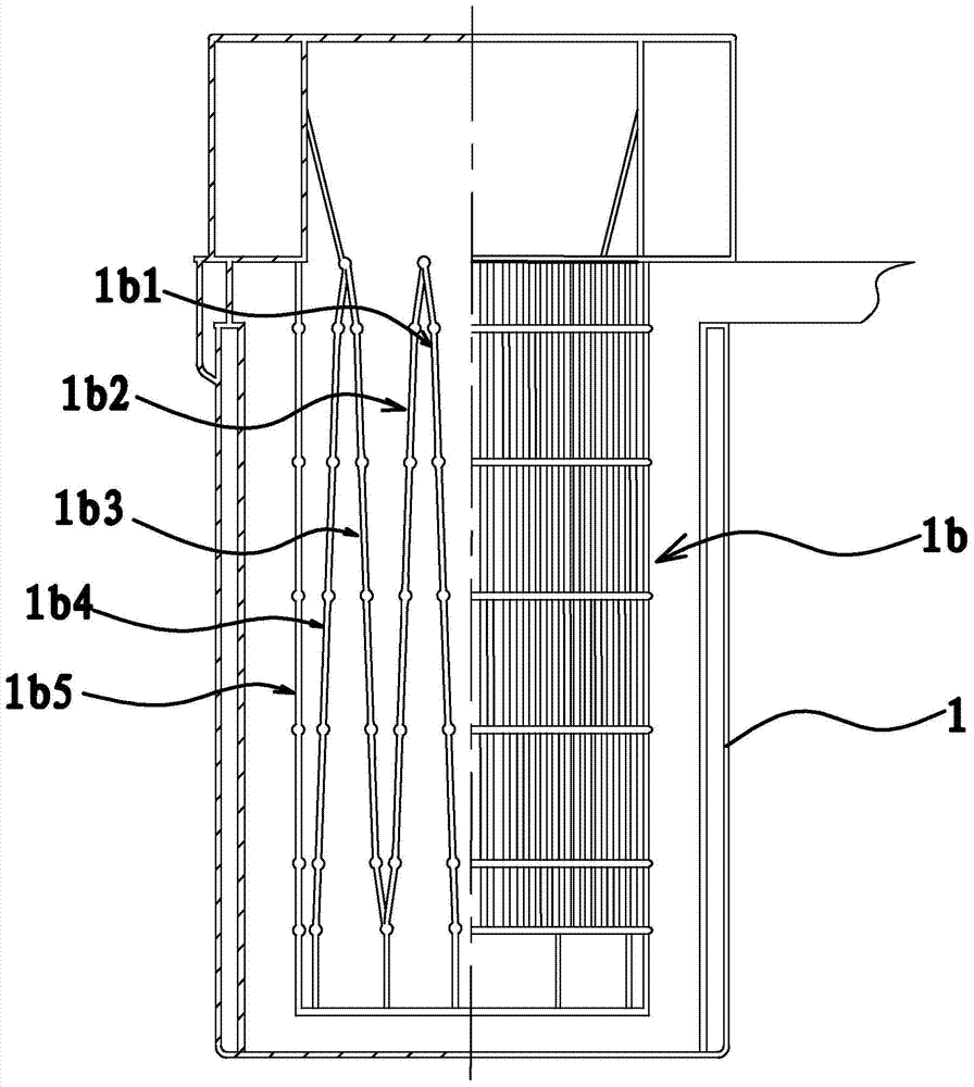
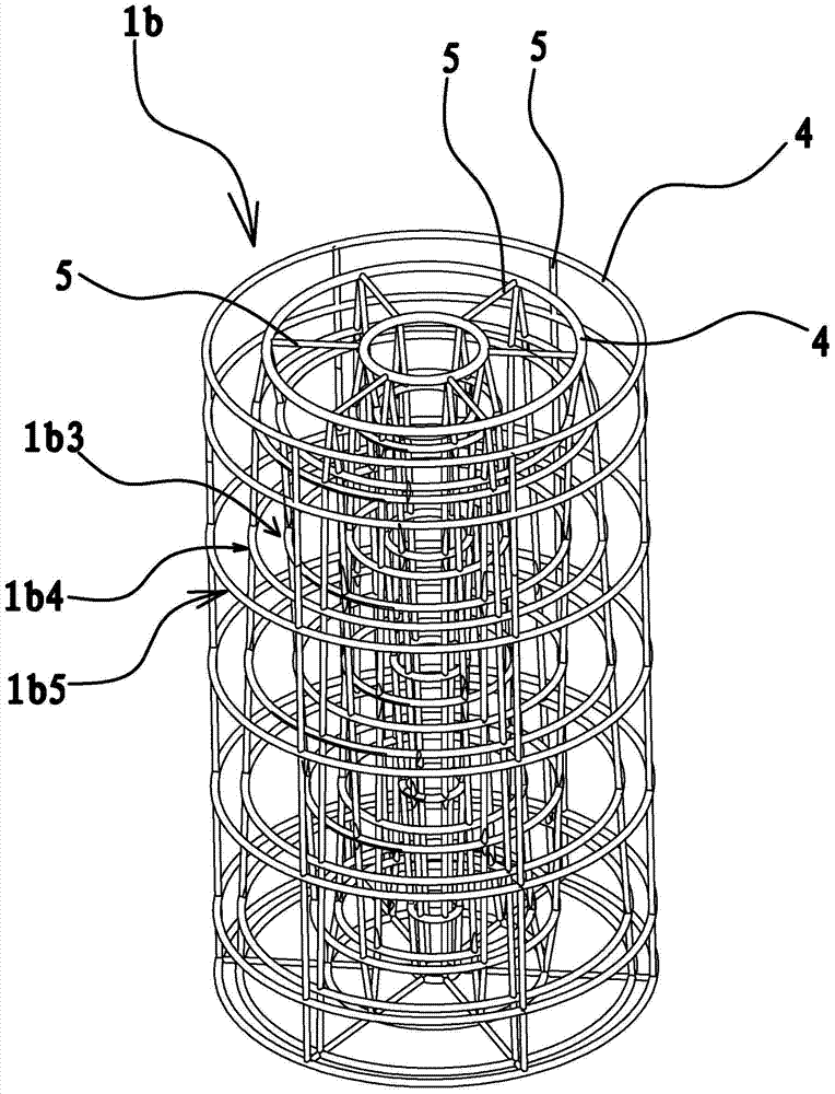
[0035] Such as figure 1 , figure 2 and image 3 As shown, a combustion frame 1b is fixed inside the tower body 1, and the combustion frame 1b is located above the combustion chamber 1a. The combustion frame 1b includes a layer of circular tube group 1b1, a second layer of circular tube group 1b2 and a triple layer of circular tube group 1b3 A layer of circular pipe group 1b1 includes several cold water circular pipes 4 wh...


PUM


Abstract

The invention provides a garbage burning apparatus, and belongs to the technical field of machinery, for solving the problem of accumulation of garbage in a furnace body due to quite slow burning efficiency of a conventional garbage incinerator. The garbage burning apparatus comprises a tower body, a smog processor and an induced draught fan, wherein the tower body is provided with a smoke pipe, the upper end of the tower body is provided with a garbage feeding port, a combustion frame is fixed in the tower body, the combustion frame is disposed above a combustion chamber, the combustion frame comprises a first layer of circular pipe groups, the first layer of circular pipe groups comprise a plurality of cold water circular pipes which have circle centers disposed at the same coaxial line and are distributed from top to bottom and a plurality of cold water straight pipes which are connected between adjacent two cold water circular pipes, the internal diameter of a circular ring formed by each cold water circular pipe is gradually decreased from top to bottom, and the cold water circular pipes communicate with adjacent cold water straight pipes. The garbage burning apparatus can effectively burn garbage and is high in burning efficiency.

Description

technical field [0001] The invention belongs to the technical field of machinery and relates to a waste incineration device. Background technique [0002] At present, there are two main methods of garbage disposal: one is landfill, and the other is incineration. Although the landfill method is relatively simple, it has many disadvantages such as large floor area, large labor and capital costs, and long decay time. Relatively speaking, incineration is a relatively advanced treatment method. The incineration method can deal with wastes of different natures, and the volume of wastes can be reduced by more than 90% after incineration. The equipment of existing incineration process garbage is basically an incinerator, as long as the garbage is poured into the incinerator to burn during work. However, the disadvantages of the incinerator are that due to the high moisture content of the garbage, the combustion temperature in the furnace is low, the garbage is incompletely burned...

Claims


Application Information

Patent Timeline
Patent Type & Authority Patents(China)
IPC IPC(8): F23G5/00F23G5/44F23G5/46F23J15/02
CPCF23G5/00F23G5/44F23G5/46F23J15/02
Inventor 冯必敖
Owner 冯必敖
Learn More