
Clutch type lock and keys

A clutch type and key technology, which is applied in the field of clutch type lock head and the key matched with the lock head, can solve the problems of small amount of lock cylinder keys, high key mutual opening rate, complex structure of lock cylinder, etc., and achieve low manufacturing cost , strong security, small size effect

Active Publication Date: 2015-09-16
徐明达
View PDF6 Cites 4 Cited by
  • Summary
  • Abstract
  • Description
  • Claims
  • Application Information

AI Technical Summary

Problems solved by technology

Although some clutch-type lock heads and pin lock cylinders disclosed at present can solve the basic anti-theft function, the mutual opening rate of keys is high, the key quantity of the lock cylinder is small, and the structure of the lock cylinder is complicated, and the processing is difficult. Therefore, it is necessary to design a lock with strong anti-technical opening ability and large amount of encoded information.

Method used


Image

  • Clutch type lock and keys
  • Clutch type lock and keys
  • Clutch type lock and keys

Examples


Embodiment 1

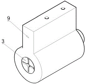
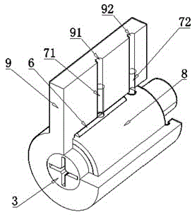
[0042] Such as Figure 1 to Figure 3 The shown lock head includes a clutch type lock cylinder, a transmission mechanism and a lock sleeve.

[0043] The bottom of the lock sleeve 9 is cylindrical, and the outer wall of the lock sleeve 9 is provided with two pin holes connected to the inside of the lock sleeve, which are respectively a jack pin hole 91 and a limit pin hole 92, and a slidable jack is placed in the jack pin hole 91. Pin 71, a slidable stop pin 72 is placed in the stop pin hole 92, and the two pin holes can be set as blind holes, and a spring is installed between the bottom of the blind hole and the top pin 71 and the stop pin 72 (not shown in the figure). ), to facilitate the movement of the ejector pin 71 and the limit pin 72. The inner wall of the sleeve of the locking sleeve 9 is provided with a groove, the groove extends in the axial direction, and the groove intersects with the pin hole.

[0044] The transmission mechanism includes an inner sleeve 8, an eje...

Embodiment 2

[0066] Such as Figure 18 As shown, in this embodiment, the structure of the guide shaft 301 and the key 101 is different from that of Embodiment 1. The key 101 has only one rack, and there are four kinds of gear blocks with different heights on the rack, and the corresponding guide shaft 301 is also corresponding. There is only one bar-shaped hole, and each coding piece has a reset block and 4 layers of stepped tooth grooves. One of the tooth grooves of the same layer of coding pieces meshes with one of the tooth pieces, but on each coding piece, the clutch groove Grooves are different from the same position of the cogs. Other structures are the same as in Embodiment 1.

Embodiment 3

[0068] Such as Figure 19 As shown, in the present embodiment, the structures of the encoding piece and the key 102 are different from those in the first embodiment. Each encoding piece has a reset block and a tooth groove, and there are 4 racks on the key 102, and each rack has a There is only one kind of tooth block, but on each coding piece, the same position of the clutch groove and the tooth groove is different. Other structures are the same as in Embodiment 1.

[0069] In Embodiment 2 and Embodiment 3, since the racks on the key and the number of cogs on the encoding sheet are relatively small, although this technical method can also be realized, the amount of encoded information is relatively small. Theoretically, the value of encoding information is infinite, but in the physical design, factors such as the size of the structure, the difference in encoding angle, and the performance of processing technology should be considered for comprehensive evaluation.


PUM


Abstract

The invention discloses a clutch type clock and keys. The lock comprises a clutch type lock cylinder, a transmission mechanism and a lock sleeve, the keys are matched with the lock cylinder, the transmission mechanism comprises an inner sleeve, a lifting pin, a limiting pin and a clutch pin, the lock cylinder rotates to form a clutch through groove, the lower portion of the clutch pin enters the clutch through groove after the clutch pin is pressed by the lifting pin, the upper portion of the clutch pin is located in a strip-shaped hole of the clutch pin of the inner sleeve, and unlocking is achieved through linkage of the lock cylinder and the inner sleeve; when the lock cylinder rotates reversely to be locked, the limiting pin limits the inner sleeve to rotate continuously, the lock cylinder continuously rotates reversely to make the lower portion of the clutch pin pressed into the strip-shaped hole of the clutch pin, the upper portion of the clutch pin enters a groove of the lock sleeve, and linkage of the lock cylinder and the inner sleeve is removed. According to the clutch type clock and the keys, the lock cylinder is further improved, and the lock cylinder comprises the multiple coding plates. The clutch type clock and the keys have the advantages that the structure is simple, the transmission is stable when the lock is unlocked or locked, the coding information content of the lock cylinder is large, and the capacity of controlling technical opening is strong.

Description

technical field [0001] The invention relates to a clutch type lock head and a key matched with the lock head. Background technique [0002] Anti-theft door locks are a daily necessity. Existing anti-theft locks generally include lock operating systems, lock cylinders, and transmission mechanisms. There have been many developments and their safety performance has been greatly improved. However, in terms of structural design and stability There are still deficiencies; the lock cylinder is the most critical part of the lock, which determines the anti-theft performance of the lock head. At present, there are pin locks commonly used in daily life. , has a very high security performance against technical opening. The invention of the clutch lock head greatly improves the ability to prevent non-technical opening, especially improves the ability to prevent rotation torque damage. Although some clutch-type lock heads and pin lock cylinders disclosed at present can solve the basic a...

Claims


Application Information

Patent Timeline
Patent Type & Authority Applications(China)
IPC IPC(8): E05B15/00E05B19/08E05B37/20
CPCE05B27/08E05B37/02
Inventor 徐明达
Owner 徐明达
Learn More