
Externalinclined core pulling device of injection mold

An injection mold and oblique core-pulling technology, which is applied in the field of external oblique core-pulling devices, can solve the problems of high overall cost of the mold, occupying the internal space of the mold, and large mold shape.

Inactive Publication Date: 2015-09-16
NINGBO SHUANGLIN MOULD CO LTD
View PDF3 Cites 7 Cited by
  • Summary
  • Abstract
  • Description
  • Claims
  • Application Information

AI Technical Summary

Problems solved by technology

[0002] Undercut refers to the inclined hole, flange, hook or rib structure in which the core-pulling and demoulding direction intersects the opening and closing direction of the mold in the injection molded product; the prior art injection mold adopts an inclined top core-pulling mechanism driven by the top plate, or The oblique core-pulling mechanism driven by the horizontal slider performs oblique core-pulling and demoulding on the undercut structure of the product; since these mechanisms are all located inside the mold, they all need to occupy the internal space of the mold, which increases the shape of the mold , when the mold is in operation, it is necessary to use a large-scale injection molding machine, which leads to high overall cost of mold manufacturing and operation; therefore, the existing technology has the problems and deficiencies of large mold shape and high overall cost

Method used


Image

  • Externalinclined core pulling device of injection mold
  • Externalinclined core pulling device of injection mold
  • Externalinclined core pulling device of injection mold

Examples


Embodiment Construction

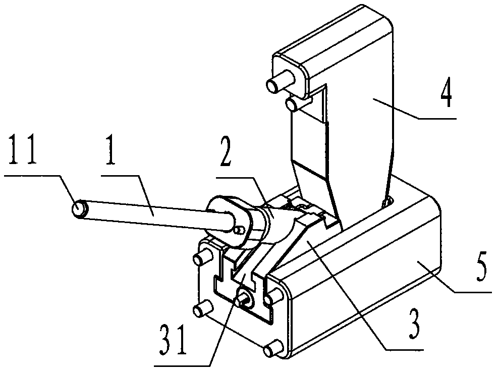
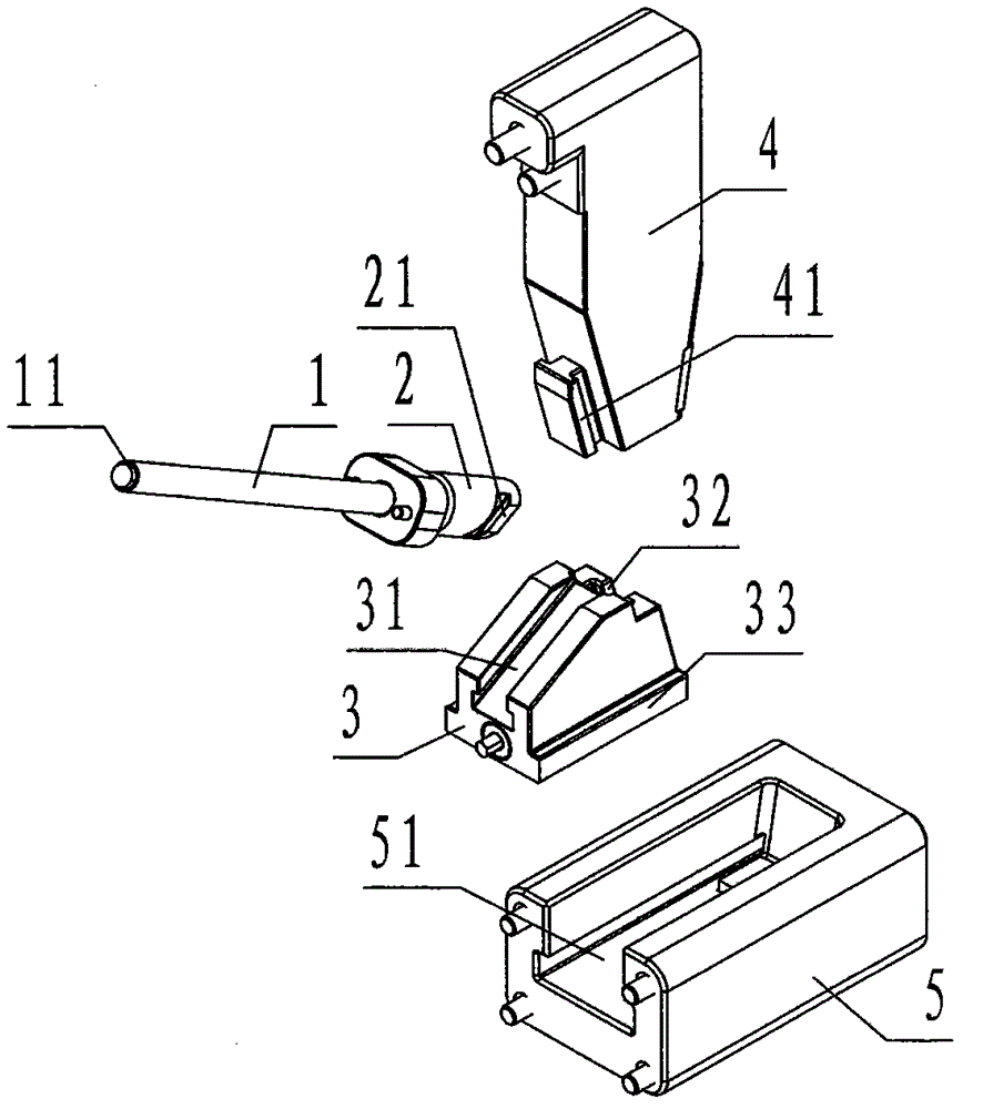
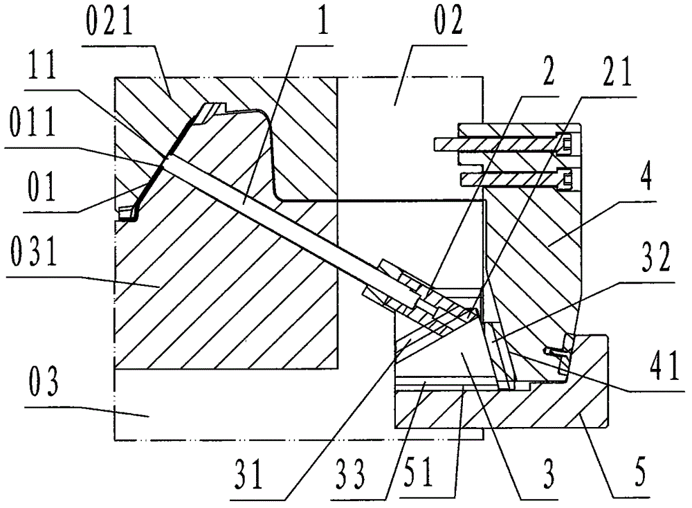
[0024] refer to Figure 1 ~ Figure 4 , an external oblique core-pulling device for an injection mold of the present invention, comprising an oblique core-pulling rod 1, an oblique sliding foot 2, a transverse slider 3, a longitudinal slider 4 and a sliding seat 5, wherein: the oblique core-pulling The core rod 1 is a cylindrical rod-shaped steel member, and the upper end of the oblique core rod 1 is provided with an oblique hole undercut 011 for forming the product 01. The sliding core is called the oblique hole core 11;

[0025] The inclined slide foot 2 is a cylindrical steel member, and the front and rear sides of the lower column wall of the inclined slide foot 2 are respectively provided with flanges inclined from left to right and whose cross section is rectangular, which are called inclined slide rails 21;

[0026] The horizontal slider 3 is a trapezoidal block-shaped steel member in the main view, and the left slope of the horizontal slider 3 is provided with a channel...


PUM


Abstract

The inventiondiscloses an externalinclined core pulling device of an injection mold. The externalinclined core pulling device comprises an inclined core pulling rod (1),an inclinedsliding foot (2), a horizontal sliding block (3), a longitudinal sliding block (4) and a sliding seat (5). According to the device, the inclined core pulling rod is connected ontotheinclined sliding foot; the inclined sliding foot is fastened onthe left inclined surface of the horizontal sliding block in a sliding manner; the horizontal sliding block is fastened on and connected with the sliding seat in a slidingmanner; the lower part of the longitudinal sliding block is fastenedon the right inclined surface of the horizontal sliding block in asliding manner; the upper part of the longitudinal sliding block is fixedly connected with theouter wall of a fixed mold loading plate; thesliding seat is fixedly connected with a movable mold loading plate; theinclined core pulling rod slides in an inclined manner and penetrates through themovable mold loading plate and a core; an inclined hole core is raised out of the upper surface of the core. During work, a mold is used for mold disassembling, the longitudinal sliding block pulls the horizontal sliding block to move rightward; the horizontal sliding block pulls theinclined sliding foot andtheinclined core pulling rod to move rightwards and downwardsso as to pull the inclined hole core out of a product in an inclined manner. According to the technical scheme, for the injection moldto be subjected to inclined core pulling, the aims that the shape of the mold is reducedand the comprehensive cost is reduced can be achieved.

Description

technical field [0001] The invention relates to a core-pulling and demoulding device for an injection mold, in particular to an external injection mold device for obliquely extracting a core block embedded in an undercut structure of a product without occupying the inner space of the mold. Inclined core pulling device. Background technique [0002] Undercut refers to the inclined hole, flange, hook or rib structure in which the core-pulling and demoulding direction of the injection molded product intersects with the opening and closing direction of the mold; the prior art injection mold adopts an inclined top core-pulling mechanism driven by the top plate, or The oblique core-pulling mechanism driven by the horizontal slider performs oblique core-pulling and demoulding on the undercut structure of the product; since these mechanisms are all located inside the mold, they all need to occupy the internal space of the mold, which increases the shape of the mold , just need to u...

Claims


Application Information

Patent Timeline
IPC IPC(8): B29C45/33B29C45/40
CPCB29C45/33B29C45/40
Inventor 许晴勇俞泽华林俊张湖
Owner NINGBO SHUANGLIN MOULD CO LTD
Learn More