
An industrial waste gas treatment system

A technology for treating system and industrial waste gas, which is applied in the direction of air quality improvement, use of liquid separation agent, separation of dispersed particles, etc., which can solve the problems of difficult control of reaction conditions.

Inactive Publication Date: 2017-03-15
ANQING HONGTAI NEW MATERIAL
View PDF5 Cites 0 Cited by
  • Summary
  • Abstract
  • Description
  • Claims
  • Application Information

AI Technical Summary

Problems solved by technology

However, pure biofilm treatment needs to hang a large amount of biofilm, and the reaction conditions are not easy to control.

Method used


Image

  • An industrial waste gas treatment system

Examples


Embodiment Construction

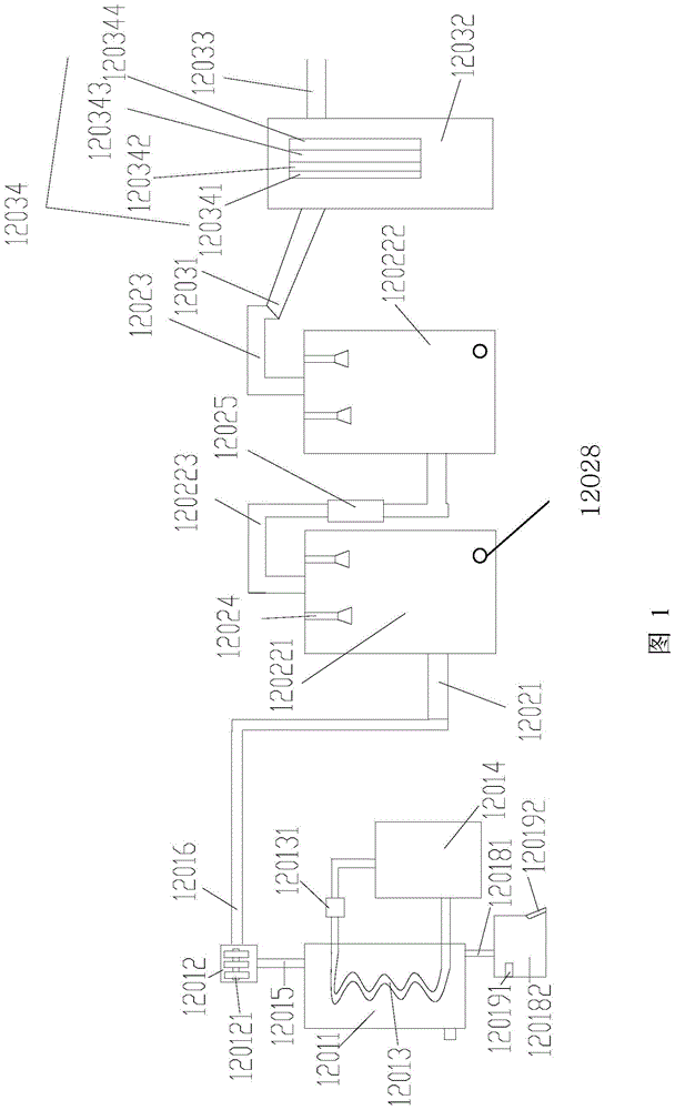
[0023] like figure 1 As shown, this embodiment includes a high-temperature exhaust gas treatment device, a spray purification exhaust gas device, and a deodorizing device from front to back.

[0024] The high-temperature exhaust gas treatment device includes a ventilation tank 12011 , a second tube condenser 12012 , a coil pipe 12013 and a refrigeration system 12014 . The lower end of the ventilation tank 12011 is provided with an air inlet, the coil 12013 is spirally arranged in the inner cavity of the ventilation tank 12011, the bottom of the coil 12013 is provided with a water inlet, and the coil 12013 is provided with a water inlet. The top of 12013 is provided with a water outlet, and both the water inlet of the coiled pipe 12013 and the water outlet of the coiled pipe 12013 extend to the outside of the vent tank 12011. The water inlet of the coil 12013 is connected with the water outlet of the refrigeration system 12014 , and the water outlet of the coil 12013 is connec...


PUM


Abstract

The invention discloses an industrial waste gas treatment system. The system comprises a high-temperature waste gas treatment device, a waste gas spray purification device and a deodorization device from front to back in sequence, wherein the high-temperature waste gas treatment device comprises a ventilation tank, a second pipe bundle condenser, a coil pipe and a refrigerating system; the waste gas spray purification device comprises a first intake pipe, at least a spray main device and a second exhaust pipe; the deodorization device comprises a third intake pipe, a deodorization main device and a third exhaust pipe; a plurality of biological membranes are hung in a cavity inside the deodorization main device; the outlet of the third intake pipe is communicated with the air inlet of the deodorization main device; the air outlet of the deodorization main device is communicated with the third exhaust pipe. The system has the advantages of high purification efficiency, good purification effects and capability of effectively removing malodorous substances in waste gases.

Description

technical field [0001] The invention relates to the field of waste gas treatment, in particular to an industrial waste gas treatment system. Background technique [0002] A large amount of waste gas is produced in industrial production. If the exhaust gas is not treated in time, it will not only affect the normal production of the factory, but also cause serious pollution to the environment, and even bring safety hazards to the factory staff and the surrounding residents. At present, waste gas generally adopts thermal combustion method, catalytic combustion method, condensation method, spray method and biological method. [0003] The thermal combustion method fully mixes organic waste gas and fuel gas at high temperature to achieve complete combustion. It is suitable for treating combustible gases with high concentration and small gas volume. It has high purification efficiency and organic waste gas will be oxidized and decomposed at the bottom. However, it has the disadva...

Claims


Application Information

Patent Timeline
Patent Type & Authority Patents(China)
IPC IPC(8): B01D53/00B01D47/06B01D53/18B01D53/85
CPCY02A50/20
Inventor 王文耕
Owner ANQING HONGTAI NEW MATERIAL
Learn More