Turnable device
A technology of turntable and mounting part, which is applied in the direction of measuring devices, instruments, and measuring electrical variables, etc. It can solve the problems that the conduction mechanism hinders the stable equal potential of the turntable part and the ground part, and is difficult to maintain.
- Summary
- Abstract
- Description
- Claims
- Application Information
AI Technical Summary
Problems solved by technology
Method used
Image
Examples
Embodiment approach 1
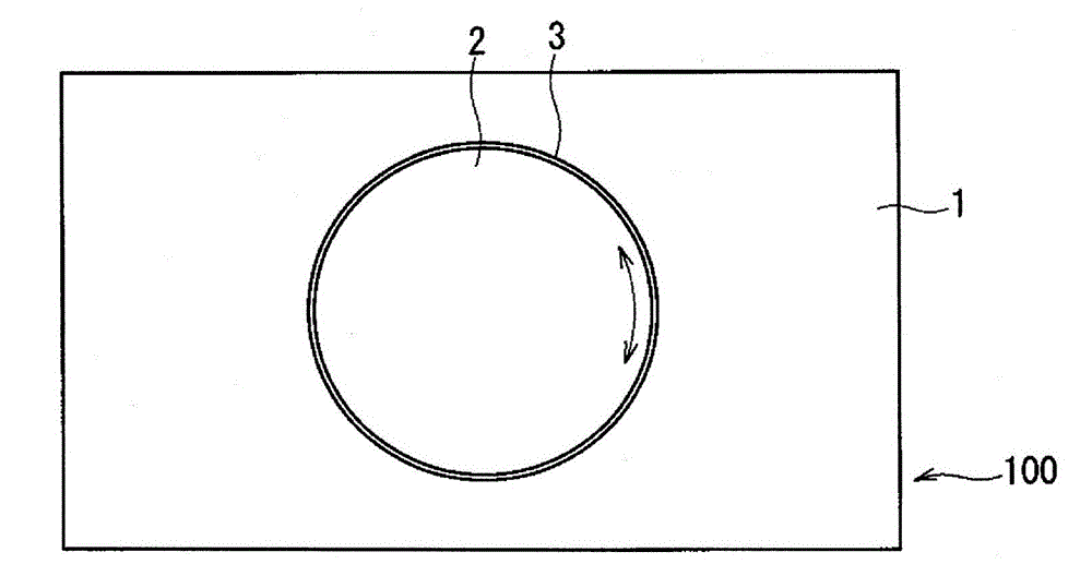
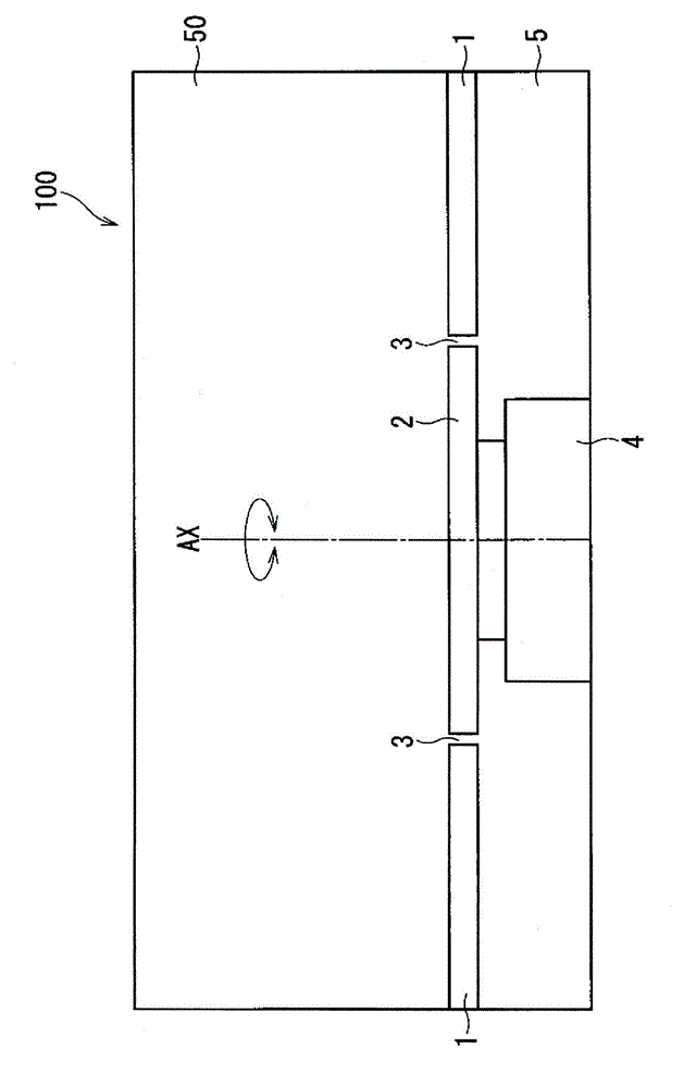
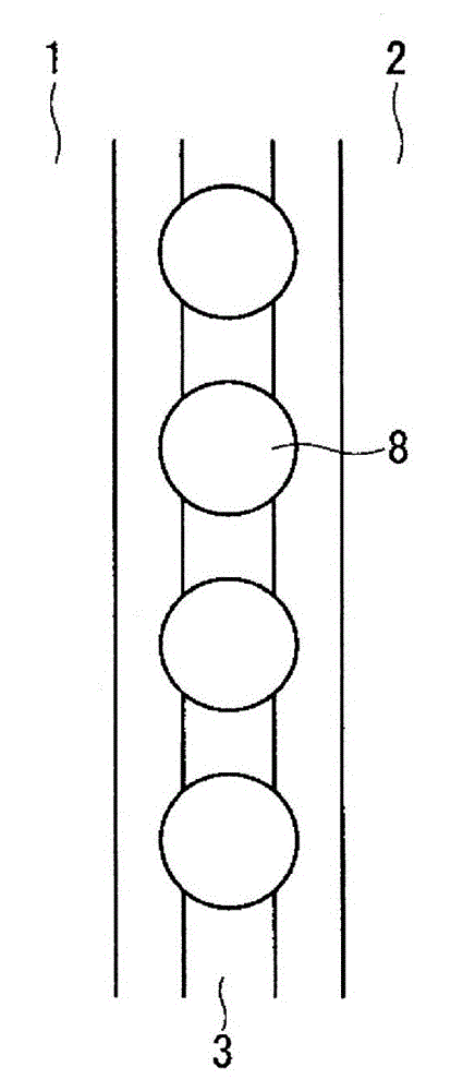
[0041] image 3 It is a plan view showing the structure of the conduction mechanism included in the turntable device according to the present embodiment. also, Figure 4 is a cross-sectional view showing the structure of the conduction mechanism. here, image 3 , 4 is shown in figure 1 , 2 An enlarged view of a part of the gap 3 is shown, including the surrounding structure of the part.
[0042] like image 3 , 4As shown, a conductor 8 is arranged as a conduction mechanism. Conductor 8 is arranged so as to be in contact with both floor portion 1 and turntable portion 2 . Furthermore, when the turntable part 2 rotates, the conductor 8 rolls with respect to the floor part 1, maintaining the said contact, and also rolls with respect to the turntable part 2. As shown in FIG. That is, the conductor 8 is not fixed anywhere, but can freely roll in the gap 3 . The specific structure of this embodiment is as follows.
[0043] In the present embodiment, the floor portion 1 h...
Embodiment approach 2
[0065] Image 6 It is a sectional view showing the structure of the conduction mechanism included in the turntable device according to the present embodiment. here, Image 6 is shown figure 1 , 2 An enlarged view of a part of the gap 3 is shown, including the surrounding structure of the part.
[0066] like Image 6 As shown, a conductor 8 is arranged as a conduction mechanism. This conductor 8 is arranged so as to be in contact with both the floor portion 1 and the turntable portion 2 . Furthermore, when the turntable part 2 rotates, the conductor 8 rolls with respect to the floor part 1, maintaining the said contact, and also rolls with respect to the turntable part 2. As shown in FIG. That is, the conductor 8 is not fixed anywhere, but can freely roll within the gap 3 (more specifically, within the conductor mounting portion 12 described later). The specific structure of this embodiment is as follows.
[0067] In this embodiment, the floor part 1 is comprised from t...
Embodiment approach 3
[0098] In this embodiment, the eaves portion 15 is added to the turntable device according to the second embodiment. Figure 7 It is a sectional view showing the structure of the conduction mechanism included in the turntable device according to the present embodiment. here, Figure 7 is shown figure 1 , 2 An enlarged view of a part of the gap 3 is shown, including the surrounding structure of the part.
[0099] Compare Image 6 and Figure 7 It can be seen that the eaves portion 15 is additionally provided in the turntable device according to the present embodiment. like Figure 7 As shown, the eaves portion 15 covers the conductor mounting portion 12 from above. In addition, the eaves portion 15 is made of, for example, a non-conductive resin or the like.
[0100] here, in Figure 7 In the structural example of , the eaves portion 15 is connected to the ground portion 1 side, but not to the turntable portion 2 side. Additionally, with Figure 7 The structure is di...
PUM
 Abstract
Description
Claims
Application Information
 - Generate Ideas
- Intellectual Property
- Life Sciences
- Materials
- Tech Scout
- Unparalleled Data Quality
- Higher Quality Content
- 60% Fewer Hallucinations
Browse by: Latest US Patents, China's latest patents, Technical Efficacy Thesaurus, Application Domain, Technology Topic, Popular Technical Reports.
© 2025 PatSnap. All rights reserved.Legal|Privacy policy|Modern Slavery Act Transparency Statement|Sitemap|About US| Contact US: help@patsnap.com


